
 HOME
HOME
ID : 2640
Installation Guide for Upright Setting of RC8A Controller
When placing the controller in the upright position, it is recommended to use customer-prepared parts to fix the controller to the wall and floor as shown below.
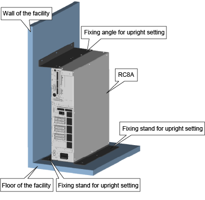
Items Prepared by Customers
| Type | A | B | |
|---|---|---|---|
| Placement direction | When the wall locates bottom side of the controller. |
When the wall locates upper side of the controller.
|
|
| Models except UL-Listed ones | Angle | Fixing angle for upright setting A (PDF:33KB) | Fixing angle for upright setting B (PDF:33KB) |
| Stand | Fixing stand for upright setting (PDF:36KB) | ||
| UL-Listed model | Angle | Fixing angle for upright setting A (PDF:24KB) | Fixing angle for upright setting B (PDF:24KB) |
| Stand | Fixing stand for upright setting (PDF:25KB) | ||
| Fixing bolt for facilities | M6 x 9 bolts (common for both types) | ||
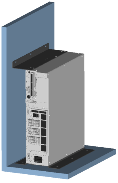
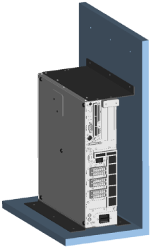
Dimensional Drawing for Fixing to the Wall and Floor
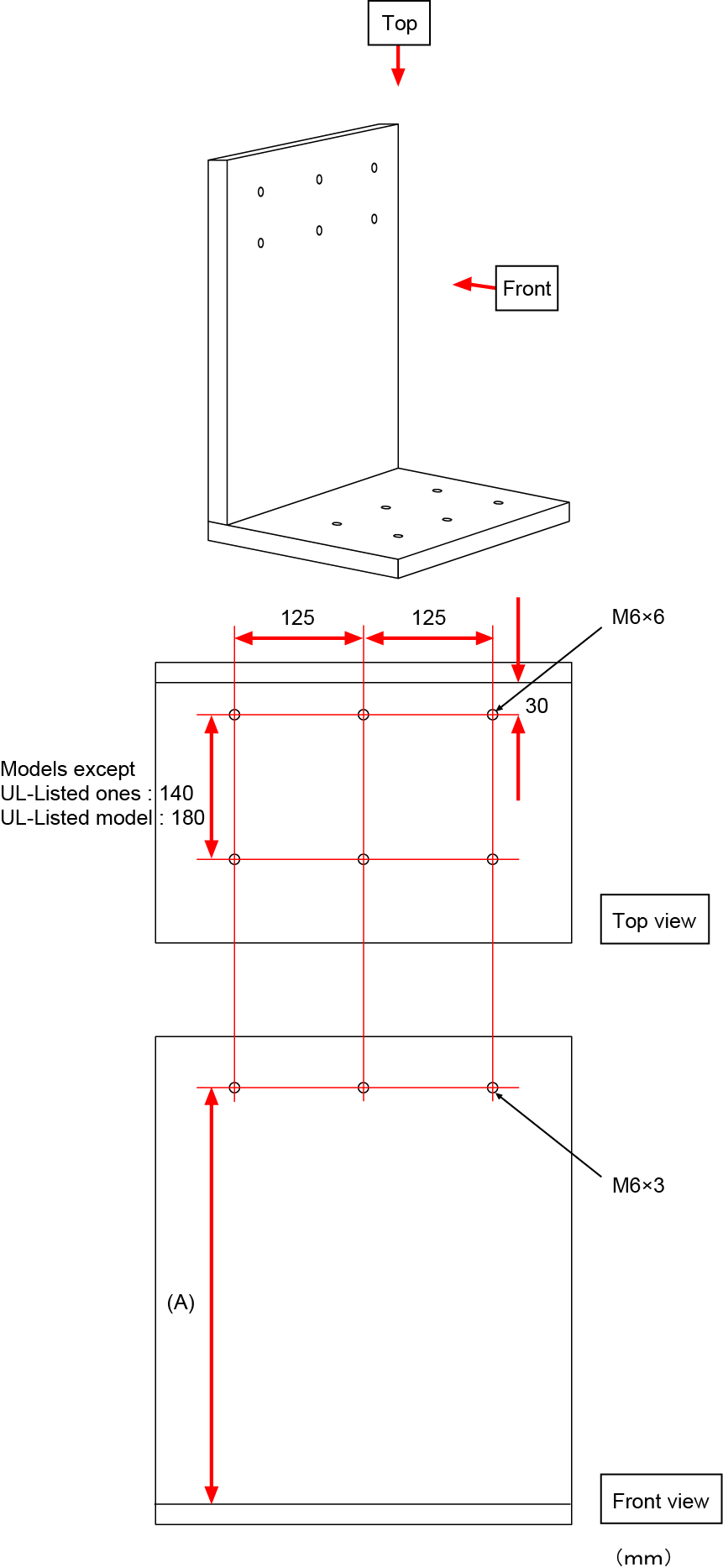
*(A) : Measurement
| Type | available controller | (A) |
|---|---|---|
| Models except UL-Listed ones | Standard, Safety I/O-less | 381 |
| Safety motion | 434.5 |
|
| UL-Listed model | Standard, Safety motion | 434.5 |
Setting Procedure
1
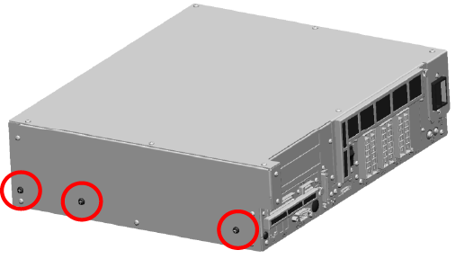
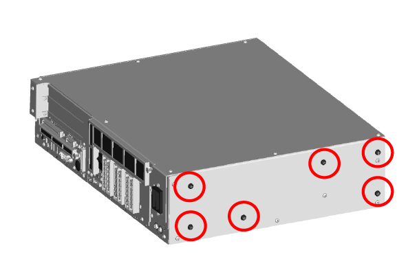
There are two types of screws, large and small, on each side panels.
Please remove large screws which are circled on the below image.
2
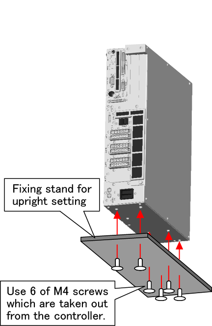
Fix the fixing stand for upright setting to the side panel which is immediately next to the power supply connector.
Use screws which are removed in STEP1.
Tightening Torque : 1.4Nm
3
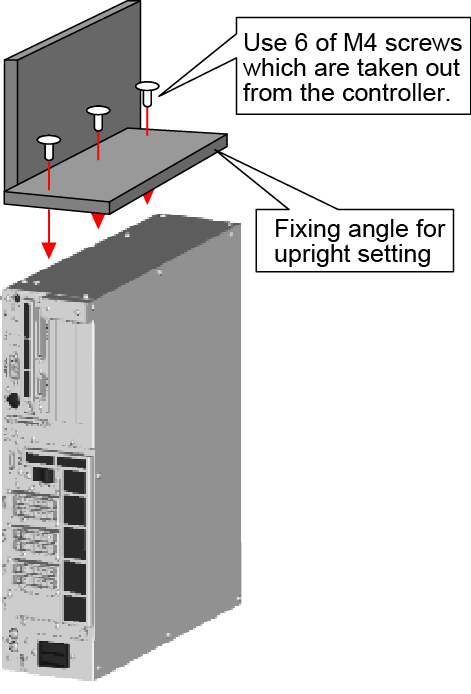
Fix the fixing angle for upright setting to another side panel.
4
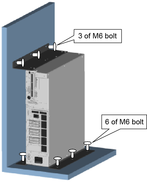
Fix the controller to the facilities' floor with 6 pieces of M6 bolts, and to the wall with 3 pieces of M6 bolts.
ID : 2640