
VM-6083-W/VM-60B1-W
Pin Assignment Layout
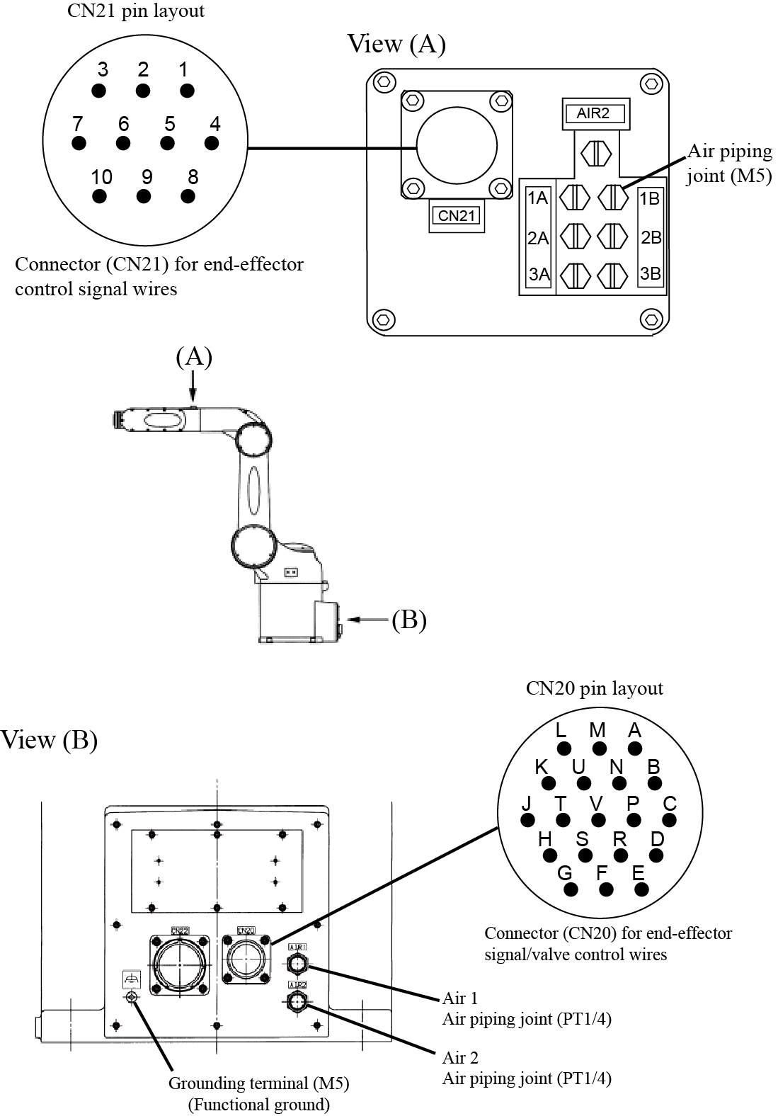 |
Valve Signals and Air Intake and Exhaust States
1A and 1B are piping joint symbols.
| Air piping joint | Valve signal | ||||
|---|---|---|---|---|---|
| AIR1 | Air intake | Exhaust | Solenoid valve | Solenoid | |
| A | B | ||||
| 1A | 1B | 1 | ON | OFF | |
| 1B | 1A | 1 | OFF | ON | |
| 2A | 2B | 2 | ON | OFF | |
| 2B | 2A | 2 | OFF | ON | |
| 3A | 3B | 3 | ON | OFF | |
| 3B | 3A | 3 | OFF | ON | |
| AIR2 | - | ||||
CN20 Pin Assignment
| CN20 pin No. | Used for: | |
|---|---|---|
|
For controller I/O unit, NPN type (source IN, sink OUT) |
For controller I/O unit, PNP type (sink IN, source OUT) |
|
| M | +24V | 0V |
| N | Solenoid 1A (solenoid valve 1) | |
| P | Solenoid 1B (solenoid valve 1) | |
| R | Solenoid 2A (solenoid valve 2) | |
| S | Solenoid 2B (solenoid valve 2) | |
| T | Solenoid 3A (solenoid valve 3) | |
| U | Solenoid 3B (solenoid valve 3) | |
Pin Number Correspondence Table between CN20 and CN21
Pins A to K on CN21 and pins #1 to #10 on CN20 are connected with each other as shown below. The allowable current per line is 1 A.
| CN20 | A | B | C | D | E | F | G | H | J | K |
|---|---|---|---|---|---|---|---|---|---|---|
| CN21 | 1 | 2 | 3 | 4 | 5 | 6 | 7 | 8 | 9 | 10 |
Connectors
Use the attached connector sets for CN20 and CN21.
| Connector set part No. | Part No. | Model and part name | Appearance | |
|---|---|---|---|---|
| 410889-0010 | 410877-0120 (for CN20) |
H/M3106A22-14S (straight plug) HIROSE ELECTRIC CO., LTD. |
|
|
| 410877-0130 (for CN20) |
H/MS3057-12A (cord clamp) HIROSE ELECTRIC CO., LTD. |
Applicable wire dia. φ11.4-15.9 |
|
|
| 410877-0140 (for CN20) |
H/MS3057-12A1 (cord clamp) HIROSE ELECTRIC CO., LTD. |
Applicable wire dia. φ8-11.6 |
||
| 410877-0070 (for CN21) |
EBLP1610M (L type plug connector) DDK Electronics, Inc. |
|
||


