
Name of Each Section of Controller
Name of each section of robot controller is described here.
Power switches and connectors to devices are concentrated in the front side. Refer to the table below for their names.
Ventilation port to release heat inside the controller is located in the rear side.
Models Except UL-Listed Ones
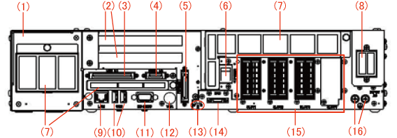
| Number | Label | Name | Purpose | Remarks | ||
|---|---|---|---|---|---|---|
| 1 | - | Safety I/O | ||||
| 2 | - | Expansion board slot (2 slots) | Install expansion board. PCI board is installed to upper slot and PCI Express board to lower slot. |
|||
| 3 | MINI I/O | Mini I/O user, system connector | *1 | |||
| 4 | HAND I/O | Hand I/O connector | *1 | |||
| 5 | PENDANT | Pendant connector | Install teach pendant and mini-pendant. | *2 | ||
| 6 | POWER | Power switch | Used for power ON and OFF of controller. | |||
| 7 | - | Intake filter | Prevent invasion of dust to inside controller. 3 locations. | |||
| 8 | INPUT AC | Power connector | Connect power cable. | *1 | ||
| 9 | LAN | Ethernet connector | Use for communication with outside device through Ethernet circuit. | |||
| 10 | USB | USB connector (2 lines) | Connect with USB memories or USB devices. | |||
| 11 | RS-232C | Serial communication connector | Use for serial communication with outside devices. | |||
| 12 | VGA | VGA connector | Use for output images. (Option) |
|||
| 13 | P (POWER) R (RUN) E (ERR) |
Status display LED | Check status of controller. | |||
| POWER | Controller power ON | Green lamp turns ON. | ||||
| Power OFF | Turn OFF. | |||||
| RUN | Program is running in Auto mode | Green lamp turns ON. | ||||
| Other | Turn OFF. | |||||
| ERROR | Robot errors and warnings (See Error Levels) |
Red lamp turns ON. | ||||
| Other | Turn OFF. | |||||
| 14 | ENC | Encoder connector | Connect encoder cable. | *1 | ||
| 15 | SLOT1, SLOT2, SLOT3, SLOT4 | Motor connector | Connect motor cable. | *1 | ||
| 16 |  |
Earth terminal (protective earth) | Protect from electric shock. | *1 | ||
*1 DO NOT connect or disconnect connectors to/from the controller when the AC power or the 24 VDC power for I/O is being supplied. Doing so may cause electric shock or controller failure. Do not unplug connector within 6 seconds of the shut down.
*2 Before unplugging connector, make sure to perform appropriate disconnection procedure. For information about disconnection procedure, refer to "Displaying Setting Menu for Pendant and Panel".
UL-Listed Model
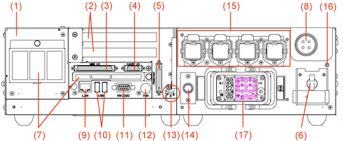
| Number | Label | Name | Purpose | Remarks | ||
|---|---|---|---|---|---|---|
| 1 | - | Safety I/O | ||||
| 2 | - | Expansion board slot (2 slots) | Install expansion board. PCI board is installed to upper slot and PCI Express board to lower slot. |
|||
| 3 | MINI I/O | Mini I/O user, system connector | *1 | |||
| 4 | HAND I/O | Hand I/O connector | *1 | |||
| 5 | PENDANT | Pendant connector | Install teach pendant and mini-pendant. | *2 | ||
| 6 | POWER | Power switch | Used for power ON and OFF of controller. | |||
| 7 | - | Intake filter | Prevent invasion of dust to inside controller. 3 locations. | |||
| 8 | INPUT AC | Power connector | Connect power cable. | *1 | ||
| 9 | LAN | Ethernet connector | Use for communication with outside device through Ethernet circuit. | |||
| 10 | USB | USB connector (2 lines) | Connect with USB memories or USB devices. | |||
| 11 | RS-232C | Serial communication connector | Use for serial communication with outside devices. | |||
| 12 | VGA | VGA connector | Use for output images. (Option) |
|||
| 13 | P (POWER) R (RUN) E (ERR) |
Status display LED | Check status of controller. | |||
| POWER | Controller power ON | Green lamp turns ON. | ||||
| Power OFF | Turn OFF. | |||||
| RUN | Program is running in Auto mode | Green lamp turns ON. | ||||
| Other | Turn OFF. | |||||
| ERROR | Robot errors and warnings (See Error Levels) |
Red lamp turns ON. | ||||
| Other | Turn OFF. | |||||
| 14 | - | Encoder connector (for Extended-joint) |
Connect encoder cable for encoder HUB. Only the Extended-joint specification controller equips this connector. |
*1 | ||
| 15 | - | Motor connector (for Extended-joint) |
Connect motor cable for Extended-joint motor. Only the Extended-joint specification controller equips this connector (four pieces). |
*1 | ||
| 16 | |
Earth terminal (protective earth) | Protect from electric shock. | *1 | ||
| 17 | - | Motor and encoder cable connector | Connect motor and encoder cable. | *1 | ||
*1 DO NOT connect or disconnect connectors to/from the controller when the AC power or the 24 VDC power for I/O is being supplied. Doing so may cause electric shock or controller failure. Do not unplug connector within 6 seconds of the shut down.
*2 Before unplugging connector, make sure to perform appropriate disconnection procedure. For information about disconnection procedure, refer to "Displaying Setting Menu for Pendant and Panel".