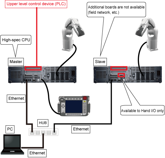
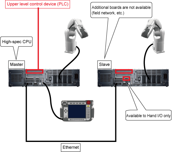
System Configuration
The figure below shows a device connection layout.
On both of the master and slave controllers, the connection methods of robot axes and/or extended-joints are the same as that of for a solely-running robot.
Connect a teach pendant to the master controller. For the slave controller, you can use the teach pendant for the initial settings only. Note that the teach pendant connected to the slave controller does not work once the initial settings have been completed and the cooperative control function is enabled.
Install a dummy connector in the pendant connector after removal of the teach pendant; otherwise, you cannot release emergency stop.
Connect the master controller and the slave controller with a LAN cable directly. Connect each LAN cable connector to the existing LAN port on respective controller.
Since controllers automatically detect the type of LAN, you can use either a straight- or a cross-LAN cable.
For the way of I/O connection, refer to "I/O Wirings".
Network Connection at Setup and Adjustment
When adjusting the robot system, you need to send and receive data between the master and slave controllers with WINCAPSIII. For the data reception/sending, use HUB as shown below since the master controller, slave controllers, and PC must be connected through LAN.