
[PNP type, other than Mini I/O dedicated mode] Mini I/O Pin Assignment
The table below lists the pin assignment of Mini I/O(PNP type) in other than Mini I/O dedicated mode.
With I/O extension board, if you use a controller in standard mode, compatible mode or user IO mode, system I/O ports (except for CPU normal I/O) turn to the user IO ports compare to the Mini I/O dedicated mode.
For standard mode and compatible mode, system I/O ports are relocated to the I/O extension board. Doing so increases available IO port number and functions of system I/O.
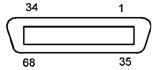
View from the cable side |
|||||||
| Terminal No. (*1) | Signal name | Port No. | Wire color | Terminal No. (*1) | Signal name | Port No. | Wire color |
|---|---|---|---|---|---|---|---|
| 1 | Enable Auto 1, -1 (input) | - | Black | 35 | Enable Auto 1, -2 (input) | - | Pink |
| 2 | External Emergency Stop 1, b-1 (input) | - | Brown | 36 | External Emergency Stop 1, b-2 (input) | - | Pink |
| 3 | External Emergency Stop 2, b-1 (input) | - | Red | 37 | External Emergency Stop 2, b-2 (input) | - | Pink |
| 4 (*2) | Protective Stop 1, -1 (input) | - | Orange | 38 (*2) | Protective Stop 1, -2 (input) | - | Pink |
| 5 (*2) | Protective Stop 2, -1 (input) | - | Yellow | 39 (*2) | Protective Stop 2, -2 (input) | - | Pink |
| 6 | Contactor Contact Monitor 1,b-1(out put) | - | Black | 40 | Contactor Contact Monitor 1,b-2(out put) | - | White |
| 7 | Contactor Contact Monitor 2,b-1(out put) | - | Brown | 41 | Contactor Contact Monitor 2,b-2(out put) | - | White |
| 8 | Deadman SW 1, -1 (output) [Enable SW 1, -1] (Safety relay) | - | Red | 42 | Deadman SW 1, -2 (output) [Enable SW 1, -2] (Safety relay) | - | White |
| 9 | Deadman SW 2, -1 (output) [Enable SW 2, -1] (Safety relay) | - | Orange | 43 | Deadman SW 2, -2 (output) [Enable SW 2, -2] (Safety relay) | - | White |
| 10 | Contactor Contact Monitor 1,a-1(out put) | - | Yellow | 44 | Contactor Contact Monitor 1,a-2(out put) | - | White |
| 11 | User input | 0 | Green | 45 | CPU Normal (System output) | 16 | White |
| 12 | User input | 1 | Blue | 46 | User output | 17 | White |
| 13 | User input | 2 | Violet | 47 | User output | 18 | White |
| 14 | User input | 3 | Gray | 48 | User output | 19 | White |
| 15 | User input | 4 | Pink | 49 | User output | 20 | White |
| 16 | User input | 5 | Black | 50 | User output | 21 | Gray |
| 17 | User input | 6 | Black | 51 | User output | 22 | Violet |
| 18 | User input | 7 | Brown | 52 | User output | 23 | Violet |
| 19 | User input | 8 | Red | 53 | User output | 24 | Violet |
| 20 | User input | 9 | Orange | 54 | User output | 25 | Violet |
| 21 | User input | 10 | Yellow | 55 | User output | 26 | Violet |
| 22 | User input | 11 | Green | 56 | User output | 27 | Violet |
| 23 | User input | 12 | Blue | 57 | User output | 28 | Violet |
| 24 | User input | 13 | Gray | 58 | User output | 29 | Violet |
| 25 | User input | 14 | Pink | 59 | User output | 30 | Violet |
| 26 | User input | 15 | Brown | 60 | User output | 31 | Gray |
| 27 | Contactor Contact Monitor 2,a-1(out put) | - | Red | 61 | Contactor Contact Monitor 2,a-2(out put) | - | Gray |
| 28 | Pendant Emergency Stop 1, b-1 (output) | - | Orange | 62 | Pendant Emergency Stop 1, b-2 (output) | - | Gray |
| 29 | Pendant Emergency Stop 2, b-1 (output) | - | Yellow | 63 | Pendant Emergency Stop 2, b-2 (output) | - | Gray |
| 30 | Reserved. | - | Green | 64 | Reserved. | - | Gray |
| 31 | Enable Auto 2, -1 (input) | - | Blue | 65 | Enable Auto 2, -2 (input) | - | Gray |
| 32 | DC power input +24V (when external power source is used) DC power output +24V (when internal power source is used) |
- | Pink | 66 | DC power input 0V (when external power source is used) DC power output 0V (when internal power source is used) |
- | Gray |
| 33 | - | Black | 67 | - | Blue | ||
| 34 | - | Brown | 68 | - | Blue | ||
*1 : The optional I/O cable for the above connector consists of twisted pair wires--pairs of #1 and #35, #2 and #36, #34 and #68.
*2 : If no Protective Stop input signals are needed, short-circuit by terminal connection with jumpers between #4 and #38 and between terminals #5 and #39.
The reserved pins and output pins should be prevented from direct contact with other pins or conductive part. Direct contact could result in a controller failure or damage.