
ID : 82
Sample Calculation in Designing End-Effectors
When calculating the moment of inertia around J4, J5 and J6 of the end-effector, use the formulas given in following Table and Figure.
Moment-of-Inertia Formulas
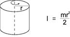
1. Cylinder (1) (Axis of rotation = Center axis) |
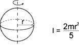
4. Sphere (Axis of rotation = Center axis) |
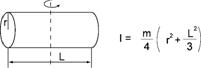
2. Cylinder (2)
(The axis of rotation passes through the center of gravity.) |
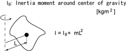
5. Center of gravity not on the axis of rotation
|
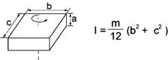
3. Rectangular parallelepiped (The axis of rotation passes through the center of gravity.) |
l : Moment of inertia [kgm2] m : Mass [kg] r : Radius [m] a, b, c, L : Length [m] |
Calculation Example
When calculating the moment of inertia of a complicated shape, divide it into simple parts as much as possible for easier calculations.
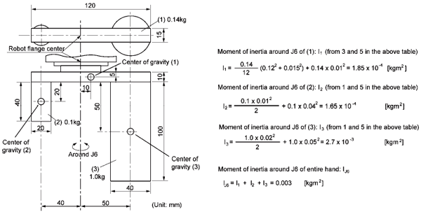
As shown in the figure below, divide the end-effector into three parts (1), (2) and (3).
Moment of Inertia Around J6
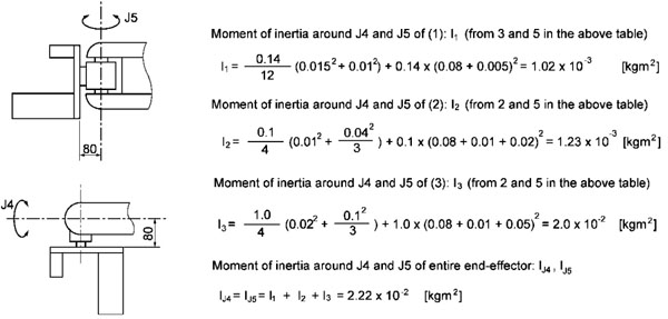
Moment of Inertia Around J4 and J5
For the end-effector shown below, the moment of inertia around J4 and J5 can be calculated according to the same formula.
ID : 82