
ID : 2621
[NPN type] Configuration of Safety Circuit for RC8A
Input signals to the safety circuit are important for safety. Be sure to configure their circuits with contacts as shown below, observing the notes given below.
For the entire scheme of safety circuit, see the followings.
RC8A : [NPN type] Safety Circuit for RC8A
Precautions on Connecting the Safety I/O
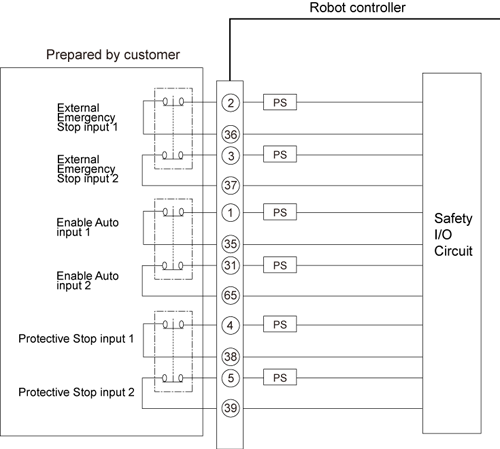
- Two External Emergency Stop input signals must be controlled with separate contacts. Two circuits connected in parallel using a single contact or an always-shorted circuit will be interpreted as an external circuit failure so that the emergency stop state cannot be reset.
- Two Protective Stop input signals and two Enable Auto input signals each must be controlled with separate contacts. Two circuits connected in parallel using a single contact or an always-shorted circuit will be interpreted as an external circuit failure so that the circuitry will not operate.
- If an inconsistency between the External Emergency Stop signal and the Enable Auto input signals, or between the Protective Stop signal and the Enable Auto input signals continues over a certain period of time(about 0.5sec), an error occurs.
Input Circuits to the Safety Circuits
 |
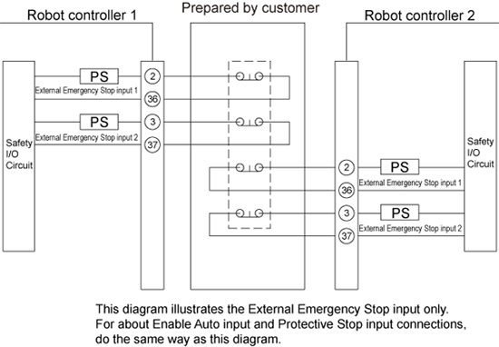
Precautions for Multiple Controllers are Used
If you use two or more controllers, the External emergency stop input of each controller must be controlled at the separate points. If these are connected to the same line, it may damage the controllers. Please refer to the following connection diagrams.
Each connection point of the enable Auto input and the Protective stop input must be controlled at the separate points as well.
 |
ID : 2621