ID : 2922
Engineering-design Notes for Robot Hands
Design the robot hands to meet the requirements described below. Otherwise, a robot failure may result.
Strictly observe these engineering-design notes. Otherwise, the clamped sections of the robot unit will become loose, rattle or be out of position. In the worst case, the mechanical parts of the robot unit and the robot controller may be damaged.
Mass of Hand
The total mass of a hand or tool (including work-piece) should be less than the maximum allowable payload of the robot.
Be sure to include the mass of wirings and piping used for a hand or tool.
| Total mass of hand or tool ≤ Max. allowable payload (incl.work-piece). (Mass of payload that you have preset) |
Hand Center of Gravity
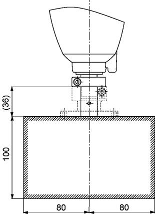
For HSA1 series, the center of gravity of a hand or tool (including work-piece) should be located within the range specified in Figure below.
|
Unit: mm |
Robot's speed and acceleration are set automatically based on the center of gravity by the safeguard of the shaft. Set the payload center of gravity and/or the payload moment of inertia beforehand. Use WINCAPSIII for confirmation of the cycle time.
Moment of Inertia Around the T Axis
The moment of inertia of a hand or tool (including work-piece) around the T axis should be less than the maximum allowable moment of inertia around the T axis of the robot.
| Hand's or Tool's moment of inertia around the T axis ≤ Max. allowable moment of inertia (incl.work-piece). |
Robot's speed and acceleration are set automatically based on the center of gravity by the safeguard of the shaft. Set the payload center of gravity and/or the payload moment of inertia beforehand. Use WINCAPSIII for confirmation of the cycle time.
ID : 2922
- Related Information
- Moment-of-inertia Formulas


