
ID : 5416
VS-6556(-B) / VS-6577(-B)
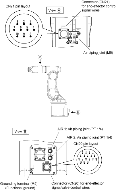
Pin Assignment Layout
 |
Valve Signals and Air Intake/Exhaust States
1A and 1B are piping joint symbols.
| Air piping joint | Valve signal | ||||
|---|---|---|---|---|---|
| AIR1 | Air intake | Exhaust | Solenoid valve | Solenoid | |
| A | B | ||||
| 1A | 1B | 1 | ON | OFF | |
| 1B | 1A | 1 | OFF | ON | |
| 2A | 2B | 2 | ON | OFF | |
| 2B | 2A | 2 | OFF | ON | |
| 3A | 3B | 3 | ON | OFF | |
| 3B | 3A | 3 | OFF | ON | |
| AIR2 | - | ||||
CN20 Pin Assignment
| CN20 pin No. | Used for: | |
|---|---|---|
|
For controller I/O unit, NPN type (source IN, sink OUT) |
For controller I/O unit, PNP type (sink IN, source OUT) |
|
| 12 | +24V | 0V |
| 13 | Solenoid 1A (solenoid valve 1) | |
| 14 | Solenoid 1B (solenoid valve 1) | |
| 15 | Solenoid 2A (solenoid valve 2) | |
| 16 | Solenoid 2B (solenoid valve 2) | |
| 17 | Solenoid 3A (solenoid valve 3) | |
| 18 | Solenoid 3B (solenoid valve 3) | |
Pin Number Correspondence Table between CN20 and CN21
Pins #1 to #10 on CN21 and those on CN20 are connected with each other. The allowable current per line is 1A.
Connectors
Use the attached connector sets for CN20 and CN21.
| Connector set part No. | Part No. | Model and part name | Appearance | ||||
|---|---|---|---|---|---|---|---|
| 410889-003* |
410887-017* (for CN20) |
SRCN6A25-24S (round type connector) Japan Aviation Electronics Industry Ltd. |
|
||||
|
410877-018* (for CN21) |
JMLP1610M (L type plug connector) DDK Electronics, Inc. |
|
|||||


ID : 5416