
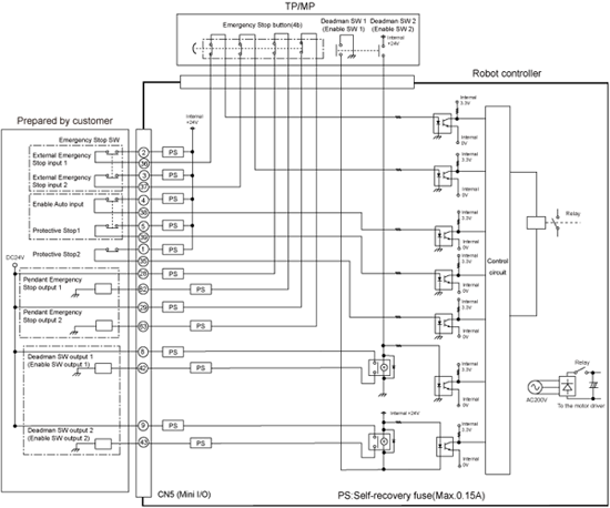
[NPN type] Emergency Stop Circuit
For Safety-I/O-less Version
The following figure shows the example of configuration and connection of emergency stop circuit on the standard type of the controller. In the RC8 controller, the emergency stop circuit consists of dual safety circuits.
The emergency stop button on the teach pendant can be used also as an emergency stop switch of the equipment.
Emergency Stop and Pendant Emergency Stop output signals
Emergency Stop output signal
The internal relay receives the External Emergency Stop input signal and the emergency stop input from the teach pendant to output this signal. When the power is turned OFF, the controller is in the emergency stop state.
Pendant Emergency Stop output signal (Dry output)
The two contacts on the emergency stop button (4b) on the teach pendant are connected. This signal will be issued independent of the ON/OFF state of the controller power.
Sample of Emergency Stop Circuit in the RC8 Controller
 |
Please refer to this if the figure is not clear.(PDF:162KB)