
Wiring of Primary Power Source
Precautions for Wiring of Primary Power Source
Observe the following precautions when wiring the primary power source of the robot controller:
About Primary Power Source
- Use the correct power source (200 VAC or 100 VAC) for the controller specification.
- Be careful not to confuse AC 100V with AC 200V (or AC 230V), and also three-phase with single-phase.
- Connect the robot power cable to a power source separate from the welder power source.
- To cut off the controller power supply, use customer-prepared-breaker.
Protective Grounding
Before connecting the power cable, make sure to connect 2.5mm2 or higher level of wire (yellow/green) to the earth terminal (protective grounding) of the front metal panel. When disconnecting the bonding wire connected to the earth terminal (protective grounding) of the front metal panel, make sure to disconnect the power cable beforehand.
Additional Precautions
- Do not bundle the teach pendant cable, I/O cables or motor & encoder cable together with high power lines such as power cables and peripheral device cables, or route the motor cables near high power devices (motor, welder, parts feeder, etc.).
- Do not route any additional cables or air tubes of end-effectors through the robot unit. Doing so will result in broken cables or tubes.
- When you connect the controller's functional grounding, ground a wire with 1.25mm2 or larger.
Robot Controller Power Supply Specifications
The following list shows the power supply specification of controllers.
Use the correct power supply for specifications below.
Be careful not to confuse AC 100V with AC 200V, and also three-phase with single-phase.
Do not use voltage greater than 240V.
Three-phase, 200V AC
| Item | Specifications | |
|---|---|---|
| Power voltage | Three-phase, 200 VAC -15% to 240 VAC +10%, 47 to 63 Hz | |
| Power supply capacity | VM: 3.3kVA | |
| VS-6556/6577: 1.8kVA | ||
| VS-068/087: 2.78kVA | ||
| VS-050/060: 1.15kVA | ||
| VP: 1.0kVA | ||
| HM: 2.45kVA | ||
| HS: 1.8kVA | ||
| XR: 1.85kVA | ||
| Max. rush current when the power is turned ON | 40 A (for 1/50 or 1/60 second) | |
| Pin assignment on power connector | A: 200 VAC, phase R (red) B: 200 VAC, phase S (white) C: 200 VAC, phase T (black) D: Protective ground (green / yellow) |
|
| Models except UL-Listed ones | 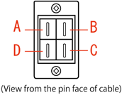 |
|
| UL-Listed model | 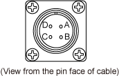 |
|
Single-phase, 230V AC
| Item | Specifications | |
|---|---|---|
| Power voltage | Single-phase, 230 VAC -10% to 240 VAC +10%, 47 to 63 Hz | |
| Power supply capacity | VS-6556/6577: 1.8kVA | |
| VS-068/087: 2.78kVA | ||
| VS-050/060: 1.15kVA | ||
| HM: 2.45kVA | ||
| HS: 1.8kVA | ||
| XR: 1.85kVA | ||
| Max. rush current when the power is turned ON | 40 A (for 1/50 or 1/60 second) | |
| Pin assignment on power connector | A: 230 VAC, phase R (red) B: 230 VAC, phase S (white) D: Protective ground (protective earth) (green / yellow) |
|
| Models except UL-Listed ones | |
|
| UL-Listed model | |
|
Single-phase, 100V AC
| Item | Specifications |
|---|---|
| Power voltage | Single-phase, AC100V-5%~AC110V+10%, 47 to 63 |
| Power supply capacity | VP: 1.0kVA |
| Max. rush current when the power is turned ON | 40 A (for 1/50 or 1/60 second) |
| Pin assignment on power connector | A: 100 VAC, phase R (red) B: 100 VAC, phase S (white) D: Protective ground (protective earth) (green / yellow)
|