
Sensor Setting
Enabling the Force Sensor
From the top screen, press [F2 Arm]-[F6 Aux]-[F1 Config]
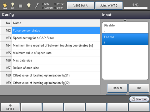
In the [Config] window, click [152 Force sensor status], and then click [Enable]-[OK].
Hardware Setting
From the top screen, press [F2 Arm]-[F5 Sensor]-[F1 Sensor Setting]
To select hardware, use the use condition parameters. For details, see the table below.
Force sensors manufactured by WACOH are shipped with the data sheets. Find a setting value from the data sheet and input it.
| No. | Item Name | Units |
|---|---|---|
| 1116 | Force corresponding value(X) | pulse/N |
| 1117 | Force corresponding value(Y) | pulse/N |
| 1118 | Force corresponding value(Z) | pulse/N |
| 1119 | Moment corresponding value(RX) | pulse/Nm |
| 1120 | Moment corresponding value(RY) | pulse/Nm |
| 1121 | Moment corresponding value(RZ) | pulse/Nm |
| 1122 | Force sensor force limit | N |
| 1123 | Force sensor moment limit | Nm |
Installation Position And The Payload Condition Setting
From the top screen, press [F2 Arm]-[F5 Sensor]-[F1 Sensor Setting]
For details, see the table below.
Setting of the Installation Position
| No. | Item Name | Units |
|---|---|---|
| 1034 | Attachment position(X) | mm |
| 1035 | Attachment position(Y) | mm |
| 1036 | Attachment position(Z) | mm |
| 1037 | Attachment position(RX) | deg |
| 1038 | Attachment position(RY) | deg |
| 1039 | Attachment position(RZ) | deg |
Specify a desired installation position with the use condition parameter. Setting value is arbitrary.
about the force sensor coordinate system, see "Force sensor coordinate system" written below.
Force Sensor Coordinate System
A force sensor coordinate system is a coordinate system defining the detection force of the force sensor or the direction of moment.
As shown below, the force sensor coordinate system is defined with the origin point of the force sensor and the direction of the coordinate axes (viewed from the TOOL0 coordinate system) in tool definition.
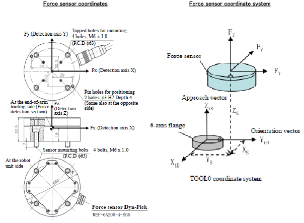
In "Force sensor coordinate" shown in the image above, the origin point of the force sensor is TOOL0 coordinate(Xs,Ys,Zs), and the direction of the coordinate axis is the direction which rotates 90 degrees around the Z-axis of the TOOL0 coordinate system. Based on that, enter (Xs,Ys,Zs,0,0,90) for the force sensor coordinates system.
Payload condition setting
| No. | Item Name | Units |
|---|---|---|
| 1297 | Force sensor Mass of payload | g |
| 1298 | Force sensor Payload center of gravity X | mm |
| 1299 | Force sensor Payload center of gravity Y | mm |
| 1300 | Force sensor Payload center of gravity Z | mm |
| 1301 | Force sensor Payload moment of inertia Ix | kgcm² |
| 1302 | Force sensor Payload moment of inertia Iy | kgcm² |
| 1303 | Force sensor Payload moment of inertia Iz | kgcm² |
Set the mass of load, the center of gravity, and the inertia through the center of gravity on the tip of the force sensor.
(e.g.) If the tip of the force sensor equips a gripper, set the total value of the gripper-mounting stay and the gripper to each component.
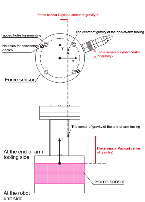
For about the position of the payload center of gravity on the tip of the sensor, refer to the figure below.
Position of the payload center of gravity
Setting of the Sensor maximum limit check function
When the robot moves with the force control, the force sensor controls in order that the applied force does not exceed its maximum rated value. However, when the robot moves without the force control, it can move at high speed without checking sensor's maximum rated value; this may damage the sensor.
The sensor maximum limit check function protects the sensor from such robot's high speed motion. Once a robot speed exceeds the specified maximum limit, an error occurs.
For about the setting, refer to the following table.
This function is available from Ver.1.8.* or higher.
| No. | Item Name | Units | Description |
|---|---|---|---|
| 1310 | Force sensor force limit | N | Set the maximum force [N] for the sensor maximum limit check function |
| 1311 | Force sensor moment limit | Nm | Set the maximum moment [Nm] for the sensor maximum limit check function |
| 1312 | Force sensor limit check | - | Enable/Disable the sensor maximum limit check function |
Checking the Force Sensor
After mounting the force sensor, check that each setting are configured as intended by using "Sensor value" which is described in the "Monitoring Function of the Force Sensor Values".