ID : 6994
Position Data
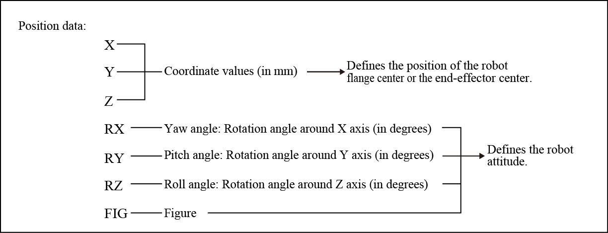
Position data refers to a set of data which includes RX, RY and five components of base coordinates (the work coordinates system if an work coordinates system is defined). Of these five components, three are robot flange center coordinates (the end-effector tip coordinates if an end-effector is defined) and two are current robot attitude components, as shown below.
Position data allows you to represent the current position of the robot flange center and object points.
 |
A set of X, Y, and Z coordinate values represents the position of the robot flange center (or tip of the end-effector if defined) expressed in base coordinates (the work coordinates system if an work coordinates system is defined) in units of mm.
The yaw, pitch, and roll angles, which are expressed by RX, RY, and RZ, refer to rotation angles around the respective axes of the base coordinate system (the work coordinates system if an work coordinates system is defined) defined by the mechanical interface coordinate system whose origin is at the center of the flange surface. These angles are expressed in units of degree.
With respect to the positive (+) direction on axes of the base coordinates, clockwise rotation is treated as positive (+).
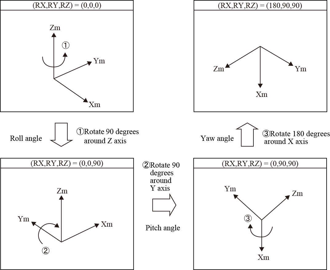
You should always preserve the rotation order of RZ, RY, and RX. Changing it will cause the robot to take a different attitude in spite of the same rotation angle defined.
The figurere presented by FIG value refers to a figure of robot arm joints. It is explained in Section, "Figures of the Shoulder, Elbow, and Wrist." You can not only select a given value, but use the Automatic figure selection function. By using this function, a robot controller automatically selects an appropriate value. For details, refer to "Automatic Figure Selection Function (Auto Fig)".
Examples of Roll, Pitch and Yaw Angle Rotation
Attitude: (RX, RY, RZ) = (0, 0, 0) → (RX, RY, RZ) = (180, 90, 90)

ID : 6994

