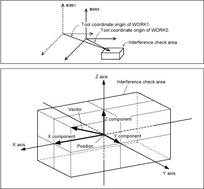
AREA
(Statement)

Declare an interference check area.

AREA <area number>,<position>,<vector>,<I/O number>,<position variable number for interference position>[,<error output>]

This statement declares an area where an interference check should be performed.
<area number> has a range of 0 to 31. Up to 32 areas can be declared.
<position> is the center position and angle of an interference check area.
<vector> is an interference check area zone whose side length is twice as long as each component of <vector>.
<I/O number> is the number of an I/O line that is turned ON by a SET command when an area interference occurs. The I/O status is maintained until a RESETAREA or RESET is executed.
In Version 1.8 or later, <I/O number> can be expressed in two forms, e.g., IO104 and IO[104]. Also, specifying -1 to <I/O number> prohibits output to the I/O line.
<position variable number for interference position> is the number of a position variable that saves the coordinates where an area interference occurs. If an area interference is detected (that is, when a SET statement turns the I/O signal ON), the system will store the origin of the current tool coordinates in work coordinates into this parameter. Usually, the origin of the tool coordinates lies on the surface of the cube; however, if the origin lies inside the cube at execution of SETAREA, the system stores that position into this parameter.
In Version 1.8 or later, <position variable number for interference position> can be expressed in two forms, e.g., P55 or P[55]. Also, specifying -1 to this parameter prohibits assignment to the position variable.
<error output> is interference check conditions to be applied when an area interference is detected.
|
<Error output>
|
The system will detect it as an error when:
|
Error signal output
|
|---|---|---|
|
0
|
The robot arm invades the defined area.
|
No
|
|
1
|
Yes
|
|
|
2
|
Yes (You can switch to Manual mode and operate the robot manually for recovery.)
|
|
|
3
|
The robot arm exits from the defined area.
|
No
|
|
4
|
Yes
|
|
|
5
|
Yes (You can switch to Manual mode and operate the robot manually for recovery.)
|
To check interference, the system compares the cube defined as an interference check area with the origin of the currently active tool coordinates. If the origin of the tool coordinates is inside the interference check area, then the system determines it as an area interference.
The interference area can be specified either in WINCAPSIII or from the teach pendant.

The center position of an area is always based on the base coordinates (WORK0).
Even if work coordinates are changed, the interference check area does not change.


6-/4-axis
|
AREA 2, P50, V10, 104, 55
|
'Define an area specified by P50 and V10 as #2
|
|
SETAREA 2
|
'Make #2 interference area detection active
|
|
RESETAREA 2
|
'Make #2 interference area detection inactive
|
6-axis
|
AREA 2, P50+(100, 100, 0, 10, 0, 0), V10, 104, 55
|
|
|
|
'Define an area specified by P50+
'(100, 100, 0, 10, 0, 0) and V50 as #2
|
|
SETAREA 2
|
'Make #2 interference area detection active
|
|
RESETAREA 2
|
'Make #2 interference area detection inactive
|
4-axis
|
AREA 2, P50+(100, 100, 0, 10), V10, 104, 55
|
|
|
|
'Define an area specified by P50+
'(100, 100, 0, 10) and V50 as #2
|
|
SETAREA 2
|
'Make #2 interference area detection active
|
|
RESETAREA 2
|
'Make #2 interference area detection inactive
|
