
Base Coordinates Setting
Set the base coordinate systems on both the master robot and slave robot.
Since the base coordinate system can be set to the leader only, designate the master robot and leader robot as a leader robot one by one, and then set the base coordinate system for both robots.
There are two ways to set the base coordinate system. One is to enter immediate values, and the other is to set with Easy Edit window.
Setting by Entering Immediate Values
1
Press the robot selection button on the top of the window to display Select Robot window shown below.
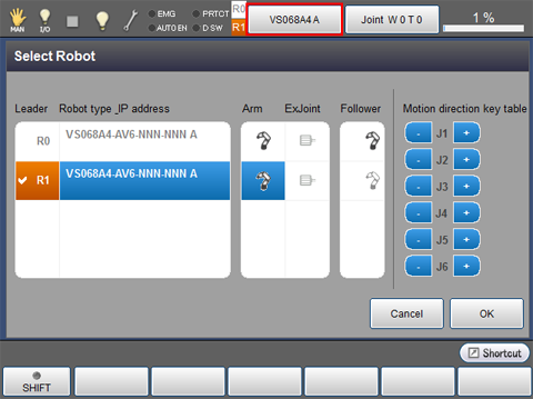
2
From the list on the center of the window, select a robot type that you want to set as a leader robot, and then press [OK].
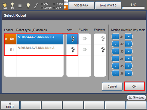
The leader robot is selected.
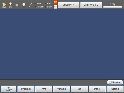
3
From the top screen, press [F2: Arm]-[F6:Aux]-[F10:Base].
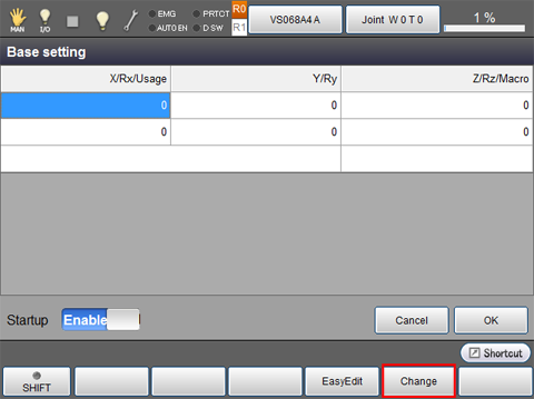
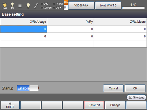
Base setting window is displayed.
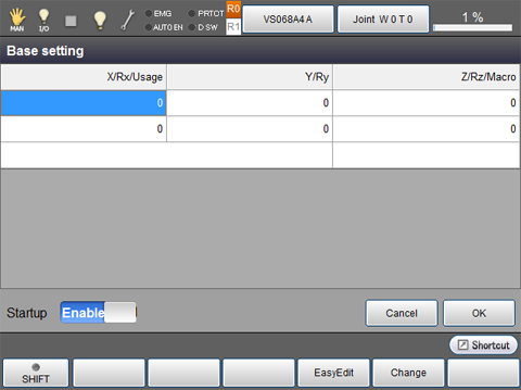
4
Select a cell you want to input, and then click [F5: Change].
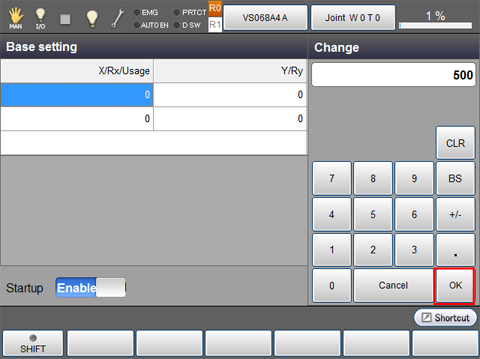
5
Once a ten key is displayed, enter the desired value with it, and then press [OK].
6
Repeat STEP4 and STEP5 to enter necessary items.
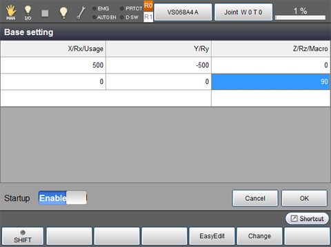
7
Once all items have been entered, check that the "Startup" is set to "Enable", and then press [OK].
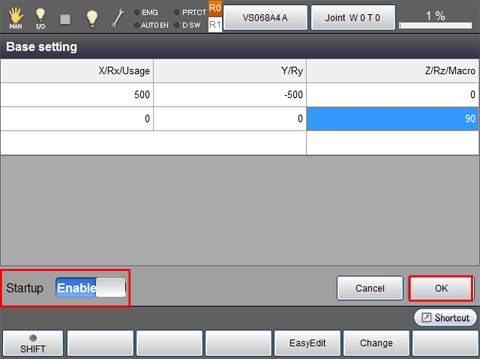
- Note that the usage cell and the macro cell are only reference. These items cannot be edited.
- Entered values are immediately reflected.
8
Once both the master and slave controller's settings have completed, reboot all controllers simultaneously.
However, if the user parameter [14: Restoration of TOOL/WORK data] has already set to [1:Enable], "Startup = Enable" will not be effective after the controller reboot. In this case, set the [14: Restoration of TOOL/WORK data] to [0: Disable] first, reboot the controller, and then set the [14: Restoration of TOOL/WORK data] to [1:Enable] again.
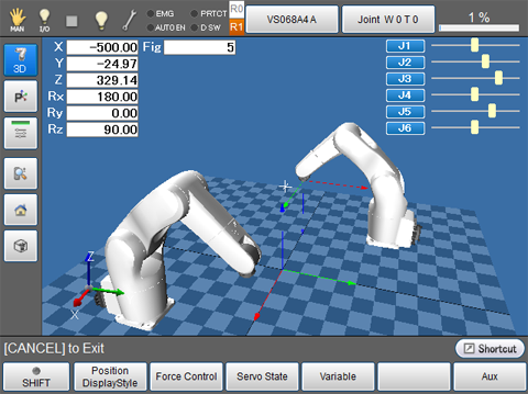
9
From the top screen, press [F2:Arm] and [LOCK] to display the three-dimension image. Check that the robots are placed in the base coordinate that you have set.
Setting with Easy Edit Window
Before the base coordinate setting, perform the teaching for arbitrary three points (an origin point, a point in the X-axis direction, and a point on the X-Y plane) as reference points and then register them to the position coordinates (P-type variables). Set the base coordinate system based on these data.
For each point, refer to the following table.
| Point on X axis | Specify a given point on the X-axis where X is greater than zero. |
|---|---|
| Point X-Y plane | Specify a given point on the X-Y plane where Y is greater than zero (the first quadrant and the second quadrant). Specifying a point where Y is smaller than zero may set the direction(s) of Y-axis and/or Z-axis to unexpected direction(s). If Y = 0 is specified, calculation result will not output because the calculation is impossible. |
1
On the Base setting window, press [F4: Easy Edit].
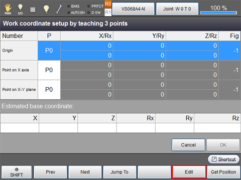
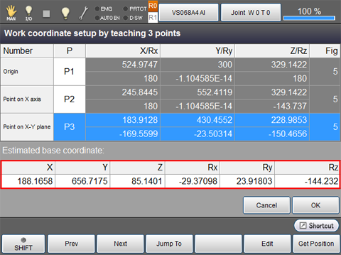
"Work coordinate setup by teaching 3 points" window is displayed.
2
Select "Origin" line and then press [F4: Edit].
3
A ten key is displayed. With the ten key, enter a variable number where origin's coordinates are stored, and then press [OK].
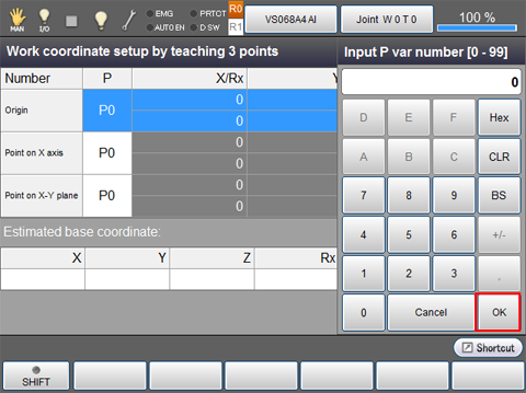
For the lines of Point on X-axis and Point on X-Y plane, enter respective variable number as well.
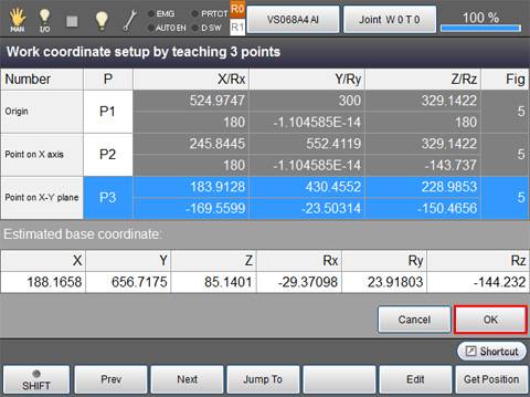
Once all points are entered, values on the "Estimated base coordinate" will be determined.
4
Once [OK] is pressed, base coordinates are confirmed.
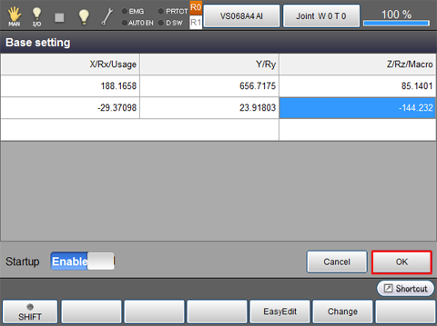
5
Check that the "Startup" is set to "Enable", and then press [OK].
6
Once both the master and slave controller's settings have completed, reboot all controllers simultaneously.
However, if the user parameter [14: Restoration of TOOL/WORK data] has already set to [1:Enable], "Startup = Enable" will not be effective after the controller reboot. In this case, set the [14: Restoration of TOOL/WORK data] to [0: Disable] first, reboot the controller, and then set the [14: Restoration of TOOL/WORK data] to [1:Enable] again.
7
For about the way of the base coordinate confirmation is same as the STEP 9 of "Setting by entering immediate values".