
ID : 10163
Specifications of Robot Unit
This section describes specifications in the following subsections.
- Product Name and Model Type
- Motion, Outer Dimensions and Weight
- Environment Conditions of Installation Site
- Structure
- Equipment for Tool
Product Name and Model Type
| Product name | VMB-2515 | VMB-2518 |
|---|---|---|
| Model type |
|
|
Motion, Outer Dimensions and Weight
| VMB-2515 | VMB-2518 | |
|---|---|---|
| Maximum motion area |
1506mm (Point P: 4th, 5th, 6th axis center) |
1804mm (Point P: 4th, 5th, 6th axis center) |
| Maximum motion range |
|
|
| Overall arm length |
710mm (first arm) + 685mm (second arm) = 1395mm |
860mm (first arm) + 835mm (second arm) = 1695mm |
| Maximum payload |
25 kg |
|
| Maximum allowable moment |
|
|
| Maximum allowable moment of inertia |
|
|
|
Position repeatability |
In each of X, Y and Z directions: ±0.05 mm (The position repeatability is the value at constant ambient temperature). |
|
|
Maximum composite speed |
13,370 mm/s | 14,000 mm/s |
| Outer dimensions | Refer to the drawing. | Refer to the drawing. |
| Weight | Approx. 230 kg | Approx. 250 kg |
*1 : 1st axis maximum motion angle when installing on the wall or tilted surface
| Model type | Tilt angle | Motion range | Model type | Tilt angle | Motion range | |
|---|---|---|---|---|---|---|
| VMB-2515 | 0° to 35° | ±170° | VMB-2518 | 0° to 30° | ±170° | |
| 35° | ±63° | |||||
| 40° | ±66° | 40° | ±52° | |||
| 45° | ±55° | 45° | ±45° | |||
| 50° | ±48° | 50° | ±41° | |||
| 55° | ±44° | 55° | ±37° | |||
| 60° | ±41° | 60° | ±35° | |||
| 65° | ±38° | 65° | ±33° | |||
| 70° | ±37° | 70° | ±31° | |||
| 75° | ±35° | 75° | ±30° | |||
| 80° | 80° | |||||
| 85° | ±34° | 85° | ±29° | |||
| 90° | 90° | |||||
| 95° | 95° | |||||
| 100° | ±35° | 100° | ±30° | |||
| 105° | 105° | |||||
| 110° | ±37° | 110° | ±31° | |||
| 115° | ±38° | 115° | ±33° | |||
| 120° | ±41° | 120° | ±35° | |||
| 125° | ±44° | 125° | ±37° | |||
| 130° | ±48° | 130° | ±41° | |||
135° |
±55° | 135° |
±45° | |||
| 140° | ±66° | 140° | ±52° | |||
| 145° to 180° | ±170° | 145° | ±63° | |||
| 150° to 180° | ±170° | |||||
| For details, refer to the graph. | For details, refer to the graph. | |||||
Environment Conditions of Installation Site
| VMB-2515 | VMB-2518 | |||
|---|---|---|---|---|
| Ambient temperature | In operation : 0 to 40°C In storage/ In transportation : -10 to 60°C |
|||
| Relative humidity | In operation : 20 to 90%RH (no dew condensation allowed) In storage/ In transportation : 40 to 75%RH (no dew condensation allowed) |
|||
| Vibration | In operation : 4.9 m/s² (0.5G) or less In storage/ In transportation : 29.4 m/s² (3G) or less |
|||
| Altitude | In operation : 1,000m or less |
|||
| Materials of the mount | Use steel materials. | |||
| Electrical noise | The robot should not be installed in any environment where;
|
|||
| Environment conditions | For Standard Type and Cleanroom TypeThe robot should not be installed in any environment where;
|
|||
For Protected TypeThe robot should not be installed in any environment where;
|
||||
Structure
| VMB-2515 | VMB-2518 | |
|---|---|---|
| Position detection | Absolute encoder | |
| Drive motor | AC servomotors for all joints | |
| Rated output of the motors |
|
|
| Brake |
|
|
| Degree of protection |
|
|
| Clean level | Cleanroom type: ISO5 |
|
| Noise (Equivalent continuous A-weighted sound pressure level) |
75dB | |
Equipment for Tool
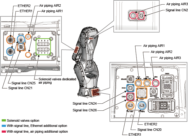
| VMB-2515 | VMB-2518 | ||
|---|---|---|---|
| Group 1 (*1) | Without solenoid valves option |
|
|
| With solenoid valves option (standard type, protected type) |
|
||
| With solenoid valves option (cleanroom type) |
|
||
| Group 2 (*1) | Without signal line, Ethernet additional option |
|
|
| With signal line, Ethernet additional option |
|
||
| Group 3 (*1) | Without signal line, air piping additional option |
|
|
| With signal line, air piping additional option |
|
||
| Air source of air piping | Operating pressure | 0.20 to 0.39 MPa | |
| Maximum allowable pressure | 0.49 MPa | ||
| *1: |
The specification of the equipment for tool is the combination of the specifications of group 1 to 3. For example, if group 1 is "with solenoid valves option (standard type, protected type)" and group 2 is "with signal line, Ethernet additional option" and group 3 is "without signal line, air piping additional option", the total specification is as below.
|
| *2: |
Do not apply the electrical current more than the allowable current of the signal line. |
ID : 10163
- Related Information
- Coding Information of Robot Model