
ID : 10671
1st-axis Mechanical End Change
At the time of delivery from the factory, mechanical ends are set in the VLA series robots so that the stroke of the 1st axis is ±180°.
Changing the mechanical ends of the 1st axis by adding mechanical stoppers is called a mechanical end change.
When you use adjustable mechanical stoppers (option), you can limit the stroke of the 1st axis in units of 15° in both directions.
The figure below shows the mechanical stopper installation positions and the stroke.
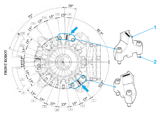
| Installation position | Negative direction | Positive direction | ||
|---|---|---|---|---|
| from [°] | to [°] | from [°] | to [°] | |
| 1 | -125 | -180 | -130 | +180 |
| 2 | -110 | -115 | ||
| 3 | -95 | -100 | ||
| 4 | -80 | -85 | ||
| 5 | -65 | -70 | ||
| 6 | -50 | -55 | ||
| 7 | -35 | -40 | ||
| 8 | -20 | -25 | ||
| 9 | -5 | -10 | ||
| 10 | +10 | +5 | ||
| 11 | +25 | +20 | ||
| 12 | +40 | +35 | ||
| 13 | +55 | +50 | ||
| 14 | +70 | +65 | ||
| 15 | +85 | +80 | ||
| 16 | +100 | +95 | ||
Components
- Adjustable mechanical stopper for 1st axis (quantity : 2)
- Hexagon socket-head bolt M20 × 90mm, strength class: 12.9 (quantity : 4)
Mounting procedure
1
Place the adjustable mechanical stopper (A) in the desired position on the robot base.
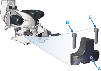
2
Tighten two fixing bolts (B) with tightening torque 674Nm.
3
If you limit the opposite side as well, mount it in the same way.
Precautions
- Remove any fixtures / piping installed on the robot that interfere with the fixing part of the adjustable mechanical stopper.
- This option can limit the 1st axis stroke in two directions. If you want to limit the stroke in only one direction, use only one of two stoppers.
ID : 10671