
ID : 11053
Safety I/O Wiring
This section describes the details of the Safety I/O in the following categories.
Wiring table
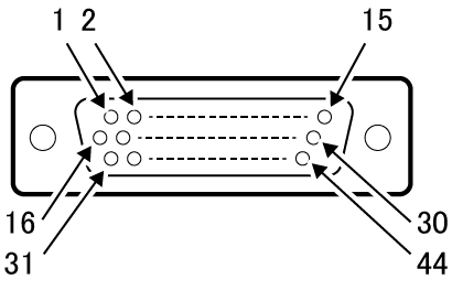
The following shows the correspondence table of the safety I/O cable terminal number and the line color.
|
Terminal number of connector (viewed from the connector mating face) |
|
|---|
| Terminal Number | Name | Wiring pair | Wire color |
|---|---|---|---|
| 1 | External Emergency Stop input 1b-1 | Pair | Black |
| 31 | External Emergency Stop input 1b-2 | Pink | |
| 2 | External Emergency Stop input 2b-1 | Pair | Brown |
| 32 | External Emergency Stop input 2b-2 | Pink | |
| 3 | Protective Stop input 1-1 | Pair | Red |
| 33 | Protective Stop input 1-2 | Pink | |
| 4 | Protective Stop input 2-1 | Pair | Orange |
| 34 | Protective Stop input 2-2 | Pink | |
| 5 | Enable Auto input 1-1 | Pair | Yellow |
| 35 | Enable Auto input 1-2 | Pink | |
| 6 | Enable Auto input 2-1 | Pair | Green |
| 36 | Enable Auto input 2-2 | Pink | |
| 7 | - | Pair | Blue |
| 37 | - | Pink | |
| 8 | - | Pair | Black |
| 38 | - | Gray | |
| 9 | - | Pair | Brown |
| 39 | - | Gray | |
| 10 | Enable switch output 1-1 | Pair | Red |
| 40 | Enable switch output 1-2 | Gray | |
| 11 | Enable switch output 2-1 | Pair | Orange |
| 41 | Enable switch output 2-2 | Gray | |
| 12 | - | Pair | Yellow |
| 42 | - | Gray | |
| 13 | Emergency Stop output 1b-1 | Pair | Green |
| 43 | Emergency Stop output 1b-2 | Gray | |
| 14 | Emergency Stop output 2b-1 | Pair | Blue |
| 44 | Emergency Stop output 2b-2 | Gray | |
| 15 | - | Pair | Violet |
| 30 | - | Gray | |
| 16 | STO monitor output 1+ | Pair | Black |
| 17 | STO monitor output 1- | White | |
| 18 | STO monitor output 2+ | Pair | Brown |
| 19 | STO monitor output 2- | White | |
| 20 | STO output 1+ | Pair | Red |
| 21 | STO output 1- | White | |
| 22 | STO output 2+ | Pair | Orange |
| 23 | STO output 2- | White | |
| 24 | EDM input+ | Pair | Yellow |
| 25 | EDM input- | White |
Signal type
The following types of Safety I/O signals are provided.
- External Emergency Stop (input)
- Protective Stop(input)
- Enable Auto input
- STO monitor output
- STO output
- Emergency Stop output signal
- Enable switch output
- EDM input
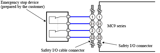
External Emergency Stop Input
To stop motors.
| Terminal Number | Contents |
|---|---|
| 1 and 31 (Line 1) |
|
| 2 and 32 (Line 2) |
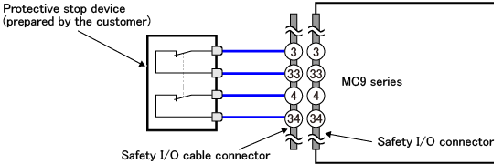
Protective Stop Input
To stop motors temporary.
| Terminal Number | Contents |
|---|---|
| 1 and 33 (Line 1) |
|
| 4 and 34 (Line 4) |
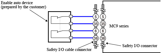
Enable Auto Input
A signal to set an MC9 series controller to AUTO mode.
| Terminal Number | Contents |
|---|---|
| 5 and 35 (Line 1) |
|
| 6 and 36 (Line 2) |
STO monitor Output, STO Output
To inform an external device of the STO state.
Emergency Stop Output signal
To inform an external device of the emergency stop input state.
Enable switch Output
To inform an external device of the enable switch state.
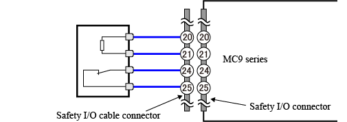
EDM Input
EDM signal monitors any failure of the STO function of an external device.
To connect this input with any device which does not equip EDM signal, connect the EDM input as the following figure shows.
ID : 11053