
ID : 18176
Wiring of the User Power Internal Power Source Connector
To wire the User Power internal power source connector, you need to disassemble the connector beforehand.
This section explains the following items.
- Disassembling of the User Power Internal Power Source Connector
- Wiring for Each Power Source Type (Internal power source /External power source)
Disassembling of the User Power Internal Power Source Connector
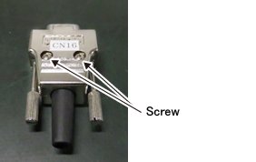
1
Place the User Power internal power source connector so that the screw heads are visible, as the following figure shows.
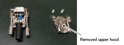
2
Remove two screws shown in the STEP1, remove the upper hood.
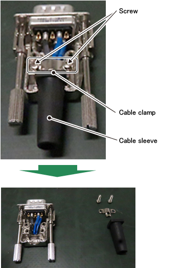
3
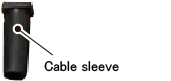
Remove two of cable clamp fixing screws, and remove the cable clamp and the cable sleeve.
4
Remove the D-sub connector part.
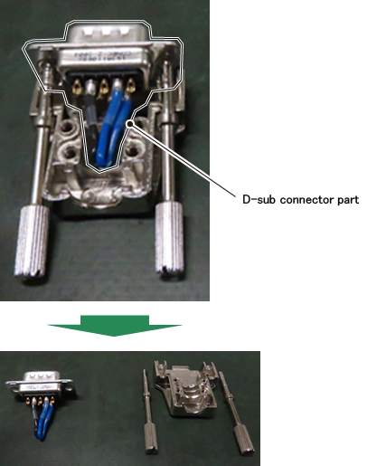
The User Power internal power source connector has been disassembled.
Wiring for Each Power Source Type (Internal power source /External power source)
Wiring for the Use of Internal Power Source
Do the wiring as the following figure shows.
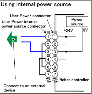
When you use a special-purpose power source (No.8 and 9 pins), do the wiring with referring to the following description.
1
Pass the cables connecting to an external device through the cable sleeve.
2
Solder cable lines connecting to an external device to the No.1 and No.3 pins of the User Power internal power source connector. If necessary, insulate the soldered part with a heat shrink tube.
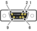
The following figure shows the terminal number of the User Power internal power source connector, viewed from the soldering part.
| Terminal number of connector (viewed from the soldering part) |
 |
|---|
3
With the reverse process of the disassembly of the User Power internal power source connector, assemble the connector.
The wiring of the User Power internal power source connector completes.
Wiring for the Use of External Power Source
Do the wiring as the following figure shows.
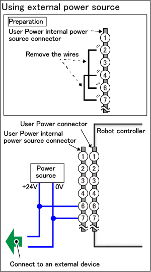
When you use a special-purpose power source (No.8 and 9 pins), do the wiring with referring to the following description.
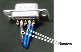
1
Remove already soldered wires (wirings that short-circuit No.2-No.6 pins and No.4-No.7 pins). As the soldered parts are covered with a heat shrink tube, remove the tube and then melt the soldering to remove the wires.
2
Pass the cables connecting to the power source and an external device through the cable sleeve.
3
Solder cable lines connecting to the power source and an external device to the No.6 and No.7 pins of the User Power internal power source connector. If necessary, insulate soldering parts with a heat shrink tube.
The following figure shows the terminal number of the User Power internal power source connector, viewed from the soldering part.
| Terminal number of connector (viewed from the soldering part) |
|
|---|
4
With the reverse process of the disassembly of the User Power internal power source connector, assemble the connector.
The wiring of the User Power internal power source connector completes.
ID : 18176