
ID : 35
Signal Wiring for Communication Interface Flange-A
Pin Assignment on CN24
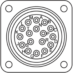
| Pin assignment on CN24 | Wiring on the flange (twisted) |
Allowable current (Allowable voltage) |
|
|---|---|---|---|
| A | Green/white | Green |
Each pin: 1.0 A or below (50 VAC or below) Total of A to M: 6.0 A or below |
| B | Yellow/white | Yellow | |
| C | White | ||
| D | Black/white | Black | |
| E | White | ||
| F | Purple/white | Purple | |
| G | White | ||
| H | Blue/white | Blue | |
| J | White | ||
| K | Red/white | Red | |
| L | White | ||
| M | Brown/white | Brown | |
| N | White |
Each pin: 0.5 A or below (50 VAC or below) Total of N to T: 1.5 A or below |
|
| P | Pink/white | Pink | |
| R | White | ||
| S | Gray/white | Gray | |
| T | White | ||
For wiring of electric grippers, refer to "Electric Gripper and Wiring to Control Board" of Electric Gripper Control board Manual (PDF:1,565KB).
ID : 35