
ID : 34
Communication Interface Flange-A
The flange has connectors for signal wiring and Ethernet (1000 BASE-T) interface. Connect them to the CN24 and Ethernet connectors on the connector panel at the robot base.
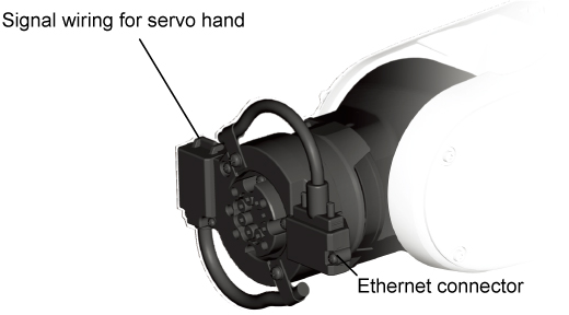
The signal lines should be used within the rated current (allowable voltage/current).
The Ethernet cable length from a device (e.g., camera) connected to the flange to a device (e.g., image analyzer) connected to the control panel should be a maximum of 20 m.
The communication interface flange-A is IP40 rated.
This flange-A is able to connect to standard type robots (IP40) only.
Selecting the communication interface flange-A uses four cores of CN20-CN21 signal wiring. Refer to "Pin Assignment on Signal Line Connectors (CN20, CN21)".
Installation Ferrite core
A ferrite core for Ethernet cable is shipped with the product. Install if the noise environment is poor or if CE conformity is required.
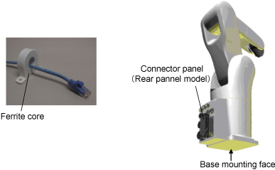
When using an Ethernet cable, install the ferrite core as close as possible to the connector panel, and then secure it with one of the tie bands provided. For the bottom connector panel model, the connector panel locates on the base mounting face.
ID : 34