
ID : 3094
Connector for Ethernet Assembly Procedure (Reference)
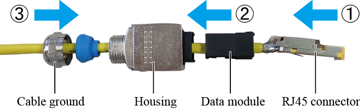
Assembly Procedure
The following shows how to assemble a connector for Ethernet.
1
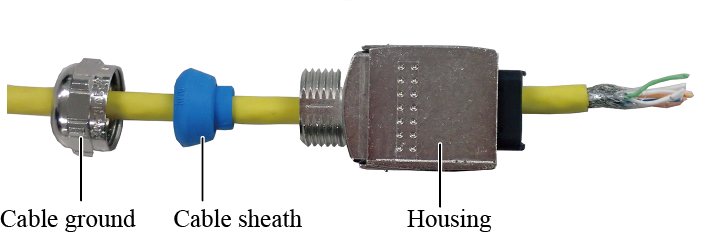
Pass a cable through a cable ground, cable sheath, housing in this order.
2
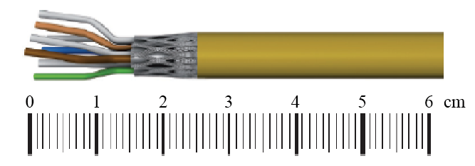
Stripe the outer jacket of the cable 24 to 26mm from the cable end.
Cut the shield braid 14 to 16mm from the cable end.
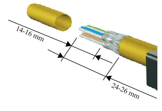
Check if the cable length and the shield length meets the length requirement.
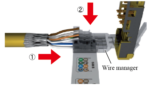
3
Insert a cable into a wire manager's port that has the same color of the inserted cable.
Arrange cables so that each cable fits the port having the same color without excessive twists.
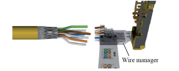
Insert the lower four cables into the ports up to the end of the wire manager.
Next, insert the upper four cables into the ports up in the same way.
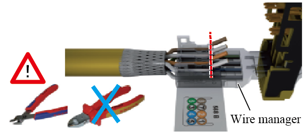
Cut the cables on the flange position of the wire manager.
Use a plier having a narrow edge.
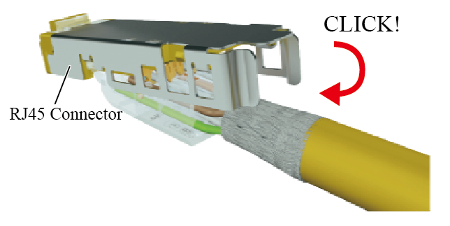
4
With holding the wire manager, fasten the wire manager's cover on the RJ45 connector.
Push the cover until it clicks.
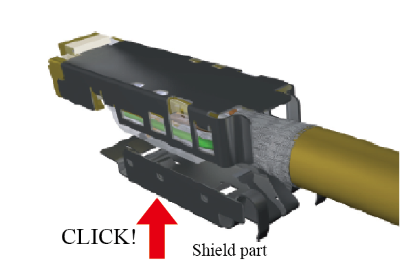
5
Fasten the shield part.
Push the shield part until it clicks.
6
Assemble each part in the following order.
- Insert the RJ45 connector into the data module until it locks.
- Insert the data module into the housing.
- Tighten up the cable ground.
Pin Number-Wire Color Combination
| Pin No. | Function / Signal | Wire color | ||
|---|---|---|---|---|
| TIA / EIA 568A | TIA / EIA 568B | Industrial (*1) | ||
| 1 | T3 | green / white | orange / whtie | yellow |
| 2 | R3 | green | orange | orange |
| 3 | T2 | orange / white | green / white | white |
| 4 | R1 | blue | blue | - |
| 5 | T1 | blue / white | blue / white | - |
| 6 | R2 | orange | green | blue |
| 7 | T4 | brown / white | brown / white | - |
| 8 | R4 | brown | brown | - |
(*1) For Ethernet profiles like PROFINET, SERCOS Ⅲ, Varan u. a.
ID : 3094