
ID : 3445
Storing of the Controller
This section describes the process to store a controller in the controller protective box Light and to connect wires.
Before operation, make sure that there is no power supply from the facilities.
The following uses RC8 standard specification controller as an example.
Recommended torque : M3:0.6N・m, M4:1.5N・m, M5:3N・m
1
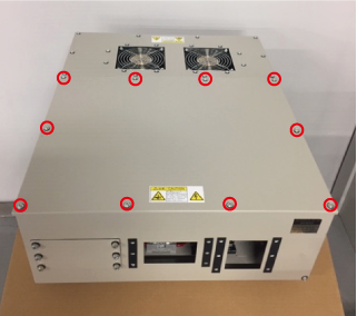
To remove the top panel B, unscrew 10 of M4 screws on the top surface.
2
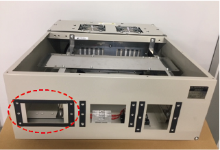
To use 13 or more cables, remove the square plate enclosed in the red dotted circle.
Please purchase rubber packing set for extended-joint cables (option part) separately and install it.
- Rubber Packing Set for Extended-Joint Cables
| Parts name | Parts number |
|---|---|
| Rubber packing set for extended-joint cables (RC8 controller protective box Light) |
410169-291* |
3
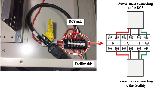
Remove the terminal board cover. Lay prepared power cable with M4 screws as shown below.
For the preparation of cables, see "Preparation of the power cable".
Once the power cable is laid, put the terminal board cover back in place.
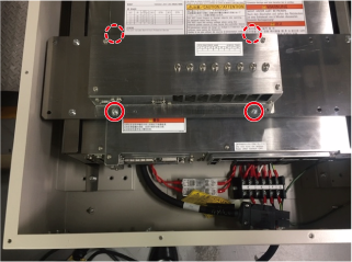
4
As the following figure shows, install the controller support bracket L on the left side of the RC8, and the controller support bracket R on the right side of the RC8, respectively. (Controller support bracket L and R are temporarily installed inside of the controller protective box Light at the shipment.)
Tighten the brackets with M4 screws, marked by six of red circles on the image below.
| Left side of the RC8 | Right side of the RC8 |
|---|---|
 |
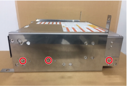 |
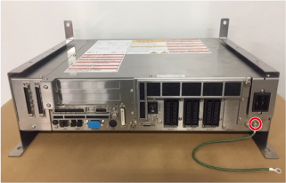
5
Connect the FG harness to the earthing point, marked by red circles (solid line) in the image below.
The image below shows the standard specification controller.
6
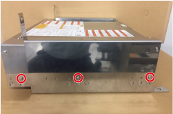
Tighten four of mounting holes on the bracket with M5 screws.
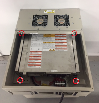
The image below shows the safety I/O less specification controller.
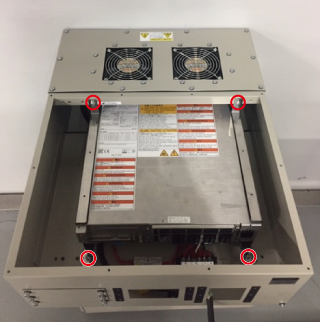
7
To use an encoder hub (option part), tighten the encoder hub with four of M4 screws marked by red circles in the image below.
8
Pass cables through the holes of multi-outlet plate EMS10 and EMS8M4 (accessory parts) and connect them to the RC8.
For information on how to attach the multi-outlet plates, see "Clamping the Cables".
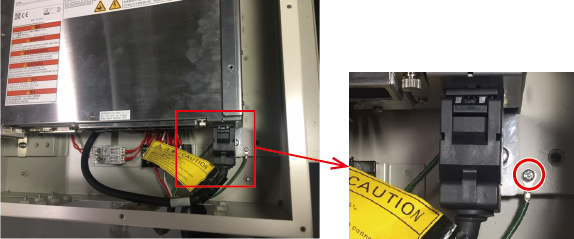
9
With an accompanied M4 screw, connect the FG harness, which you have connect in STEP5, to the circle near the terminal board.
10
Put the top plate back in place with 10 of M4 screws which was removed in the STEP1.
ID : 3445