
ID : 3446
Clamp the Cables
This section describes the process to clamp cables with the multi-outlet plate.
1
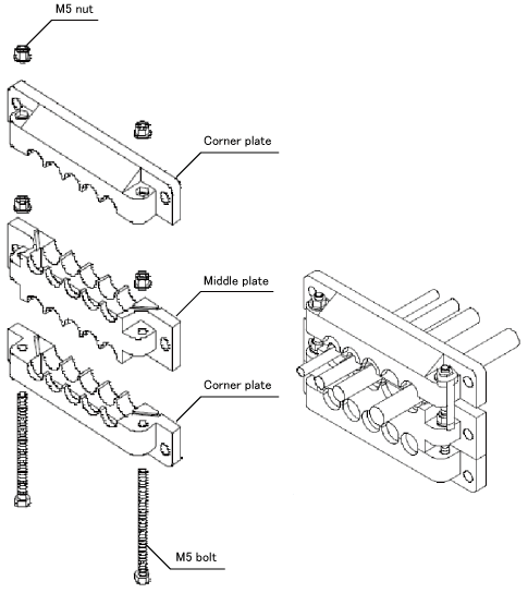
Install rubber packings in the ditches of the corner plate and the middle plate.
- Rubber Packing Set
| Model | Application cable dia | Application |
|---|---|---|
| EMSP0 | - | To be used as a blind cover |
| EMSP4 | φ4-φ6 | Communication cable |
| EMSP6 | φ6-φ8 | Pendant cable, Hand I/O cable |
| EMSP8 | φ8-φ10 | Mini I/O cable |
| EMSP10 | φ10-φ12 | Extended parallel I/O cable |
| EM28P0 | - | To be used as a blind cover |
| EM28P10 | φ10-φ12 | Power cable |
| EM28P20 | φ20-φ22 | Motor and encoder cable |
- Rubber Packing Set for Extended-Joint Cables
| Parts name | Parts number |
|---|---|
| Rubber packing set for extended-joint cables (RC8 controller protective box Light) |
410169-291* |
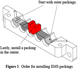
Note the following points when installing the EMS packings on the plates.
- Install the EMS packings in the ditches in order starting from both ends of the ditches to the center. (Figure 1)
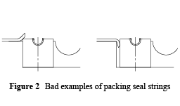
- Ensure that the ends of the packing seal strings mounted on the plates are neither lifted up by nor caught in the installed EMS packings. (Figure 2)
2
Pass the M5 bolts through the hex holes so that the head of bolts go under the hole.
3
Pass the cables through the holes between the corner plate and the middle plate. Adjust both plates to the vertical direction.
4
Attach the M5 nuts to the M5 bolts.
5
Tighten the corner plate and the middle plate with a spanner until no space remains between the plates.
6
Pass the cables through the holes between the middle plate and the corner plate. Adjust both plates to the vertical direction.
7
Attach M5 nuts to the M5 bolts.
8
Tighten the middle plate and the corner plates with a spanner until no space remains between the plates.
9
Once you finish assembly, pass the cables through the square opening part of the controller protective box Light. Pass the M6 screws through the sealing washer holes. With the M6 screws, tighten the plates from the front side of the protective box.
ID : 3446