<< Prev        Next >>

ID : 7812

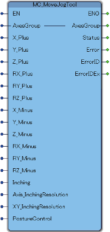
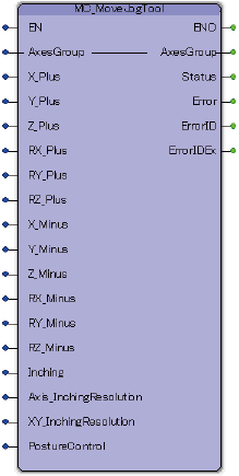
MC_MoveJogTool

To operate a robot with Tool mode from TP panel.

Graphic expression FB category
Ver.5.5 Ver.5.35
Motion

Input and Output Variable

Variable name Data type Valid range Default Omission (*)
AxesGroup eRC_AxesGroup No
Robot Group
Specify a robot variable (structured type data : eRC_AxesGroup) of user-defined type.

Input Variable

Variable name Data type Valid range Default Omission (*)
X_Plus Boolean
  • TRUE : Start
  • FALSE : -
FALSE Yes
X-coordinate (+)
When this signal changes from FALSE to TRUE, a robot moves to the positive direction of X-coordinate.
Y_Plus Boolean
  • TRUE : Start
  • FALSE : -
FALSE Yes
Y-coordinate (+)
When this signal changes from FALSE to TRUE, a robot moves to the positive direction of Y-coordinate.
Z_Plus Boolean
  • TRUE : Start
  • FALSE : -
FALSE Yes
Z-coordinate (+)
When this signal changes from FALSE to TRUE, a robot moves to the positive direction of Z-coordinate.
RX_Plus Boolean
  • TRUE : Start
  • FALSE : -
FALSE Yes
RX-coordinate (+)
When this signal changes from FALSE to TRUE, a robot moves to the positive direction of RX-coordinate.
RY_Plus Boolean
  • TRUE : Start
  • FALSE : -
FALSE Yes
RY-coordinate (+)
When this signal changes from FALSE to TRUE, a robot moves to the positive direction of RY-coordinate.
RZ_Plus Boolean
  • TRUE : Start
  • FALSE : -
FALSE Yes
RZ-coordinate (+)
When this signal changes from FALSE to TRUE, a robot moves to the positive direction of RZ-coordinate.
X_Minus Boolean
  • TRUE : Start
  • FALSE : -
FALSE Yes
X-coordinate (-)
When this signal changes from FALSE to TRUE, a robot moves to the negative direction of X-coordinate.
Y_Minus Boolean
  • TRUE : Start
  • FALSE : -
FALSE Yes
Y-coordinate (-)
When this signal changes from FALSE to TRUE, a robot moves to the negative direction of Y-coordinate.
Z_Minus Boolean
  • TRUE : Start
  • FALSE : -
FALSE Yes
Z-coordinate (-)
When this signal changes from FALSE to TRUE, a robot moves to the negative direction of Z-coordinate.
RX_Minus Boolean
  • TRUE : Start
  • FALSE : -
FALSE Yes
RX-coordinate (-)
When this signal changes from FALSE to TRUE, a robot moves to the negative direction of RX-coordinate.
RY_Minus Boolean
  • TRUE : Start
  • FALSE : -
FALSE Yes
RY-coordinate (-)
When this signal changes from FALSE to TRUE, a robot moves to the negative direction of RY-coordinate.
RZ_Minus Boolean
  • TRUE : Start
  • FALSE : -
FALSE Yes
RZ-coordinate (-)
When this signal changes from FALSE to TRUE, a robot moves to the negative direction of RZ-coordinate.
Inching Boolean
  • TRUE : Enable
  • FALSE : Disable
FALSE Yes
Inching mode setting
When this signal changes from FALSE to TRUE, inching mode is enabled.
Axis_InchingResolution Real 0.0001 to 0.1 0.0004 Yes
Set moving angle of each Joint in inching mode.
Set moving angle of each Joint in inching mode. Unit is degree.
XY_InchingResolution Real 0.01 to 1 0.01 Yes
Set moving distance for XY/Tool in inching mode.
Set moving distance for XY/Tool in inching mode. Unit is millimeter.
PostureControl Boolean
  • TRUE : Enable
  • FALSE : Disable
TRUE Yes
Posture Control
Choose enable(on) or disable(off) of posture control. In the vicinity of the singular point, it is recommended to choose off for ease of use.

(*) : For some Variable, entries can be omitted.

  • Yes : Entry can be omitted.
  • No : Entry required always.

Output Variable

Variable name Data type / Description
Status Boolean
JOG motion state
TRUE : Jogging state
FALSE : Not jogging state
Error Boolean
Error presence
TRUE : This FB ended abnormally.
FALSE : This FB ended successfully.
ErrorID Word
Error location
2800 (hexadecimal) : The error occurred in the PLC program.
2801 (hexadecimal) : The error occurred in the robot controller.
ErrorIDEx DWord
Error Code
This is a number to identify the error description.
For details, refer to "Error code list".

Function Description

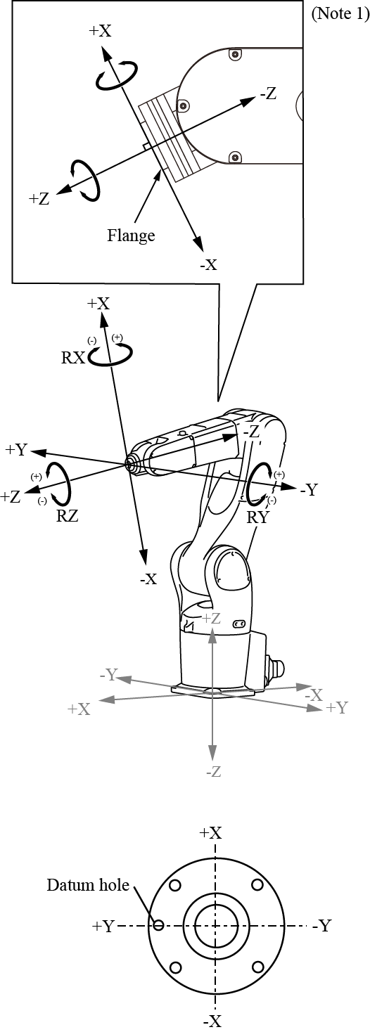
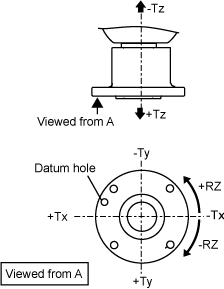
The following figure shows the robot motion in Tool mode.

6-axis robot 4-axis robot
Drives the robot flange linearly along the X-, Y-, and Z-axes of the flange face. Drives the robot flange linearly along the Cartesian coordinates of the 4th axis.

Note 1: This figure shows the tool coordinate system when Tool0 is selected. This coordinate system is called mechanical interface coordinate system.

Attention

To execute this FB, FB with the FB category "Motion" needs to be made executable.
To make FB with the FB category "Motion" executable, use the FB "MC_Power".

ID : 7812

<< Prev        Next >>