
ID : 7192
Operation Panel Screen
Main Screen
Start the operation panel after starting the robot program (TSR10.pcs).
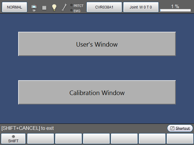
Once the operation panel is started, the main window as shown below is displayed.
To open a window to calibrate, press [Calibration Window] button.
To open a window created by user, press [User's Window] button.
Calibration screen
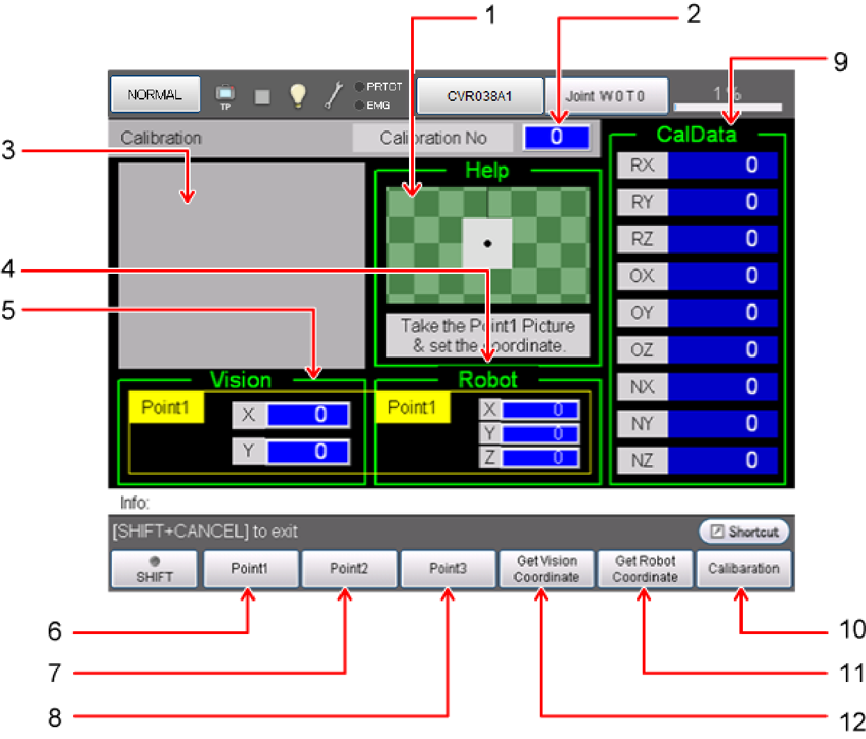
The following calibration screen is provided. It can be used for three-point teach calibration work.
Functions of Each Button
Each button functions as follows.
| 1 | Help screen. Displays a brief description of the next operation. |
| 2 | Sets the calibration number. 31 sets of calibration data can be saved. |
| 3 | Displays images taken with a camera (Displayable for a Cognex or Panasonic camera). |
| 4 | Shows the robot coordinates of points 1 to 3. |
| 5 | Shows the vision coordinates of points 1 to 3. |
| 6 | Switches to the teach coordinates (robot/vision) of point 1. |
| 7 | Switches to the teach coordinates (robot/vision) of point 2. |
| 8 | Switches to the teach coordinates (robot/vision) of point 3. |
| 9 | Displays the calibration data registered to a calibration number. |
| 10 | Calculates calibration data. |
| 11 | Gets the robot coordinates. |
| 12 | Gets the vision coordinates (the centroid position of the mark) (Available for supported visual device of four manufacturers). |
The menu displayed by pressing SHIFT is as follows.
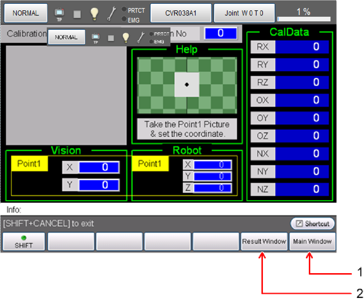
| 1 |
Switch to the main window. |
| 2 |
Switch to the result confirmation screen. The calibration result can be checked. |
Point Teach Method
A method of teaching three vision coordinates and robot coordinates separately on a one-by-one basis. Prepare a calibration jig that makes only one mark appear on the camera image and teach a set of vision coordinates and robot coordinates of points 1 to 3.
Supported visual devices of four manufacturers support automatic input of vision coordinates.
Result Confirmation Screen
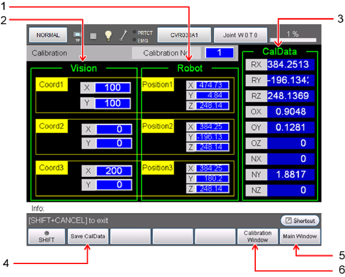
The vision coordinates and robot coordinates of the marks used to calculate calibration, and CalData obtained by calculating them can be verified and saved. Each calculation result can be verified by changing the calibration numbers (0 to 31).
| 1 | The robot coordinates registered to points 1 to 3 can be verified. |
| 2 | The vision coordinates registered to points 1 to 3 can be verified. |
| 3 | The calibration data calculated from each of the registered coordinates can be verified. |
| 4 | Saves the calculated CalData in the dedicated database. |
| 5 | Switch to the main window. |
| 6 | Returns to the Calibration window. |
ID : 7192