
ID : 10208
User Power Wiring
This section describes the details of the User Power in the following categories.
Description of Each Terminal
The following shows the terminals on the User Power internal power source connector which is shipped as a standard item.
|
Terminal number of connector (viewed from the connector mating face) |
|
|---|
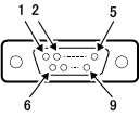
| Terminal number | Name |
|---|---|
| 1 | Internal power source +24 VDC output |
| 2 | |
| 3 | Internal power source 0 VDC output |
| 4 | |
| 6 | I/O power source +24 VDC input |
| 7 | I/O power source 0 VDC input |
| 8 | Special-purpose power source +24 VDC input (*1) |
| 9 | Special-purpose power source 0 VDC input (*1) |
*1 : Use this terminal to output the emergency stop output of the Safety I/O connector even if the robot controller is power-off.
Circuit Diagram
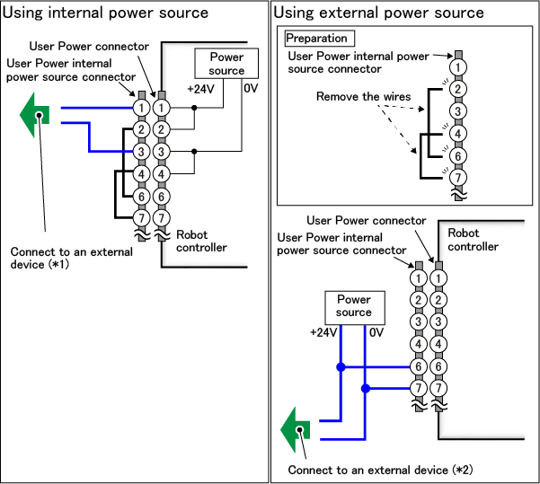
*1 : This wiring is not required if Digital I/O is not used.
*2 : If Digital I/O is not used, connection to the power source is required though, wiring to an external device is not required.
ID : 10208
- Related Information
- Wiring of the User Power Internal Power Source Connector