
ID : 10206
How to Wire I/Os
I/O Types
Robot controller equips the following I/Os as standard items.
- Safety I/O
- Safety-related I/O signals, such as external emergency stop input, protective stop input, are included in this I/O. This I/O connection is required. Robot does not move unless this I/O connects.
Therefore, you must purchase the cable for this I/O at any time. - Digital I/O
- You can start a robot program from an external device (such as a PLC) through this Digital I/O, not from the field network. To use this I/O, you need to connect a User Power.
The cable for this I/O is an option part. - Hand I/O
- This I/O is used to control an end-effector tool mounted in the robot flange (such as a robot gripper). To use this I/O, you need to connect a User Power.
The cable for this I/O is an option part. - User Power (connector)
- To use a Digital I/O or a Hand I/O, you need to prepare power source for that signal. (Hereafter, "I/O power source”). User Power is a connector that supplies I/O power source.
For the I/O power source, you can select either the power source supplied from the robot controller (internal power source) or an external power source.
When you purchase a robot controller, a connector that enables to use the internal power source (hereafter, "User power internal power source connector") is shipped as a standard item. Therefore, when you use an internal power source, insert the user power internal power source connector to the user power connector to enable Digital I/O and Hand I/O. To use an external power source, arrange the wiring of the user power internal power source connector to an external power source, and then insert the wiring to the user power connector.
Details
For more information about the pin assignment and cable wiring of each I/O, refer to the following links.
|
Item (link destination) |
Outline |
|---|---|
| Safety I/O Wiring | Describes the connector pin assignment, cable color, and circuit diagram of Safety I/O. |
| Digital I/O Wiring | Describes the connector pin assignment, cable color, and circuit diagram of Digital I/O. |
| Hand I/O Wiring | Describes the connector pin assignment, cable color, and circuit diagram of Hand I/O. |
| User Power Wiring | Describes the connector pin assignment, cable color, and circuit diagram of User Power. |
If You Make a Cable by Yourself
Use an Optional Connector
These connectors are available as individual options. Prepare by yourself a cable that meets the standards listed below to assemble the cable.
| Connector name | Optional part number | Cable standards |
|---|---|---|
Safety I/O (D-sub 44-pin 3-row) |
414880-097* |
UL2789 (With shield) AWG28 × 25P |
Digital I/O (D-sub 37-pin 2-row) |
414880-095* |
UL2789 (With shield) AWG28 × 20P |
Hand I/O (D-sub 26-pin 3-row) |
414880-096* | UL20276 (With shield) AWG24 × 15P |
User Power (D-sub 9-pin 2-row) |
414880-099* | UL20276 (With shield) AWG22 × 5P |
Use a Recommended Connector
If you do not use the optional connectors listed above, use the recommended connectors and cables listed below.
| Connector name | Connector model/manufacturer | Cable standards |
|---|---|---|
Safety I/O (D-sub 44-pin 3-row) |
Plug: 163A16619X |
UL2789 (With shield) AWG28 × 25P |
Digital I/O (D-sub 37-pin 2-row) |
Plug: 163A11099X |
UL2789 (With shield) AWG28 × 20P |
Hand I/O (D-sub 26-pin 3-row) |
Plug: 0950 200 5604 Cover: 0967 015 0344 Manufacturer name: HARTING |
UL20276 (With shield) AWG24 × 15P |
User Power (D-sub 9-pin 2-row) |
Plug: 163A11069X |
UL20276 (With shield) AWG22 × 5P |
Modify the Shielding Wire (Example)
Be sure to modify the shielding wire at the end of the cable to be used, as shown below. Without this modification, the robot may malfunction due to noise.
1
Prepare I/O cables.

2
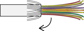
Stripe the cable jacket from the I/O cable end.

3
Fold back the braided shield, and then cut it to the proper length.
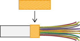
4
Wrap copper tape around the braided shield.
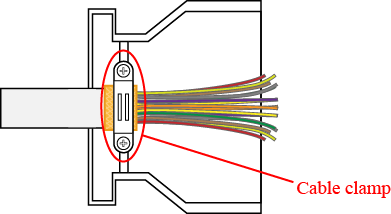
5
Position the portion of wrapped copper tape with cable clamp, so as to be tightened, and then fix it with screws.
ID : 10206
- Related Information
- Safety I/O Wiring
- Digital I/O Wiring
- Hand I/O Wiring
- User Power Wiring