
ID : 10531
Installation Precautions
Insuring the Proper Installation Environment
The standard and cleanroom types should not be installed in any environment where:
- there are flammable, explosive atmosphere
- there are any acidic, alkaline or other corrosive material,
- there are any large-sized inverters, high output/high frequency transmitters, large contactors, welders, or other sources of electrical noise.
- it may likely be submerged in fluid or exposed to water splash,
- there are any shavings from metal processing or other conductive material flying about,
- there is a mist,
- there is conductive pollution.
- it may be subjected to radiations.
- outdoor.
Service Space
The robot and peripheral equipment should be installed so that sufficient service space is maintained for safe teaching, maintenance, and inspection.
Also, ergonomics should be considered for equipment installation so as not to put a strain on worker’s body.
Do not get on the robot body and robot controller when working. It may cause a failure, and workers may be injured.
Control Devices Outside the Robot's Restricted Space
The robot controller, smart TP and mini-pendant shall be installed outside the robot's restricted space and in a place where you can observe all of the robot's movements and operate the robot easily.
The smart TP and mini-pendant should be installed so as to be able to distinguish each combination of the emergency stop switch and the robot to prevent pressing wrong emergency stop switches when you stop the robot by the emergency stop switch.
To prevent misuse, properly keep the smart TP and mini-pendant that are not connected.
Positioning of Gauges
Pressure gauges, oil pressure gauges and other gauges should be installed in an easy-to-check location.
Protection of Electrical Wiring and Pneumatic Piping
- If the electrical wiring or the pneumatic piping is at risk of damage, protect them with a cover or similar items.
- Be careful not to apply too much pressure on the joint.
Grounding Resistance
The protective grounding resistance of the robot power supply should not be more than 100Ω. For details, refer to pages related to grounding of each model.
- Check the voltage before turning on the robot. If you apply wrong voltage, it may cause a fire or burn-out.
- Check the connection of the grounding before turning on the robot. If the grounding is not connected, it may cause electric shock.
Grounding of Peripheral Tools
If a conductive tool (see the following examples) is placed around the robot unit or the robot controller (hereinafter called "the robot/controller") with all the following conditions for their positional relation being satisfied, ground the conductive tool to prevent electric shock.
Examples of Conductive Tools
- Metal tube
- Fence
- Ladder
- Handrail
Conditions for the Positional Relation
The robot/controller and a conductive tool are so close that a person can touch them at the same time.
A reference distance between the robot/controller and a conductive tool in which a person can touch them at the same time is 2.5 m or less.
Positioning of Emergency Stop Switches
To immediately stop the operation of robot in an emergency situation, install an emergency stop switch at a position which fulfills the following requirements according to ISO 13850.
- Where the operator can easily operate
- Where it is close to the program start button
Check that all the installed emergency stop switches work correctly.
Properly keep the emergency stop switch that is not connected so as not to be in a place where it can be operated.
Positioning of Operating Status Indicators
Operating status indicators should be positioned in such a way where workers can easily see whether the robot is on a temporary halt or on an emergency or abnormal stop.
Precautions for Transporting and Installation of the Robot Unit
- Use a crane or a fork lift with suitable capacity to perform the work in compliance with lows and regulations of each country and region.
- Pass the hoisting wires through the specified eyebolts. Passing them through other sections may drop the robot unit, resulting in a broken robot or bodily injuries.
- The workers must wear protective gear (hard hat, safety shoes, safety glasses, gloves).
- Do not stay under the robot during operation.
If you transport a robot and a robot controller in a way other than DENSO specified one, it may cause serious bodily injury or death by falling or tumbling down.
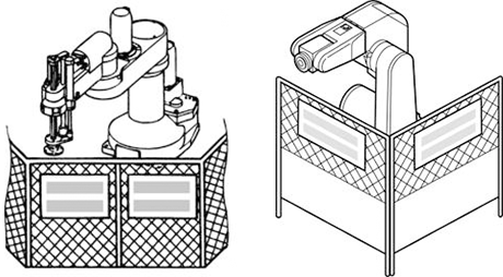
Setting-up a Safety Fence
Safety fences shall be designed and installed based on related regulations (including related notification, notice and guideline) and related standards (such as ISO 12100 and ISO 10218-2) after performing risk assessment.
Precautions at Installation (Example)
- Structure of the safety fence shall only be removable using a tool.
- Strength of the safety fence shall not be damaged/deformed by the robot running external force.
- The exit/entrance of the safety fence shall be specified. Structure of the safety fence shall be constructed so that all persons including operators cannot enter the safety fence from any places other than exit/entrance (preventing from such as climbing the fence and entering from opening of fence).
- Opening of safety fence shall be designed and installed (such as interval of lattice) so that arms and legs cannot reach hazards.
- At the exit/entrance of the safety fence, interlock devices and/or presence detection devices shall be installed.
- Install the safety fence with sufficient space kept inside so that a worker can avoid the danger when trapped inside the fence.
- When making a test run, before setting up the fence, place an overseer in a position outside the robot’s restricted space and one in which he/she can see all of the robot’s movements. The overseer should prevent workers from entering the robot's restricted space and be devoted solely to that task.
Setting the Robot's Motion Space
The area required for the robot to work is called the robot's operating space.
If the robot’s motion space is greater than the operating space, it is recommended that you set a smaller motion space to prevent the robot from interfering or disrupting other equipment.
No Robot Modification Allowed
Never modify the robot unit, robot controller, smart TP and other devices.
Cleaning of Tools
If your robot uses welding guns, paint spray nozzles, or other end-effectors requiring cleaning, it is recommended that the cleaning process be carried out automatically.
Lighting
Install appropriate lighting equipment for the robot installation area (especially, the area used for maintenance, inspection and teaching).
Also, make sure that the lighting does not generate other hazards. (For example, workers are dazzled by the reflection or blinking of lighting)
If the lighting is inappropriate, when a worker performs any operation (such as teaching and maintenance) near the robot, he or she could stumble on or hit a part of robot, leading to unexpected injury.
Protection from Objects Thrown by the End-effector
If there is any risk of workers being injured in the event that the object being held by the end-effector is dropped or thrown by the end-effector, consider the size, weight, temperature and chemical nature of the object and take appropriate safeguards to ensure safety.
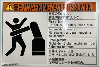
Affixing the Warning Label
Place the warning label pack¬aged with the robot on the exit/entrance of the safety fence or in a position where it is easy to see.
Posting the Moving Directions of All Axes
Post a notice showing axes names and moving directions in a visible location on the robot unit. The posted moving directions should match the actual directions. No posting or wrong direction posting may result in bodily injuries or property damages due to incorrect operation.
Changing the Configuration
When the components of the robot system or optional devices (including hardware software) have been changed or added, carry out necessary tests or inspections of safety functions.
ID : 10531