
ID : 10541
Fixing the Robot Unit
This section describes the following items.
Fixing Method
It is not expected to fix the robot directly to the floor. The mount or robot fixing plate must be installed between the robot mounting surface and the concrete surface.
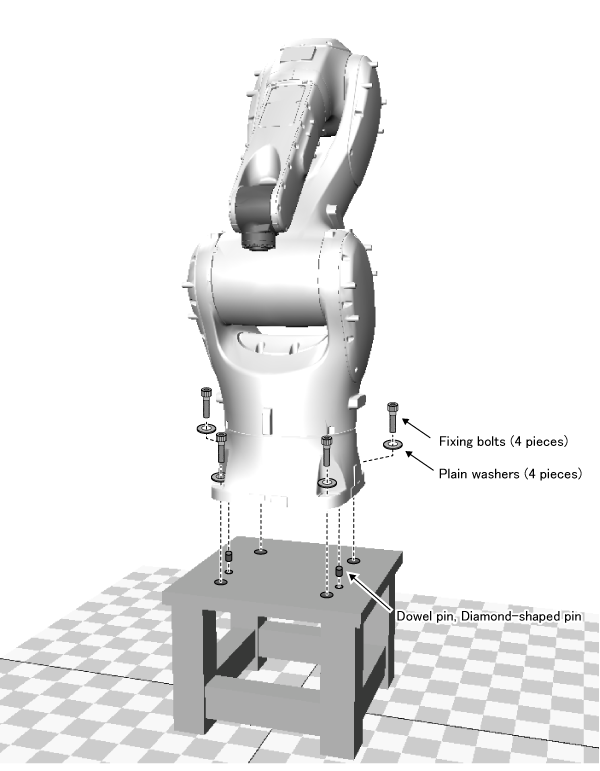
To secure the robot, use fixing bolts, the dowel pin, the diamond-shaped pin as shown in the following figure. Therefore, for the mount, you need to prepare the taps for fixing bolts and the holes for the dowel pin and the diamond-shaped pin.
When fixing, be sure to use the dowel pin, the diamond-shaped pin or the reference surface for positioning. They can minimize positional deviations when you remove and reinstall the robot unit for maintenance.
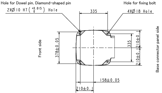
Positions of Taps and Holes
The following drawing shows the position of each hole when the robot base part is viewed from the above.
With referring to following drawing, prepare the taps for fixing bolts and the holes for the dowel pin and the diamond-shaped pin.
The tap depth should be 30 mm or more.
Fixing Bolts and Dowel pin, Diamond-shaped pin
Please prepare fixing bolts by customers. We recommend the following specifications.
- Fixing bolt
- Specification: M16×65 (Strength class: 12.9)
- Tightening torque: 317 ±63 Nm
- Plain washers
- Specification: JIS B 1256 (polished round)
Dowel pin and the diamond-shaped pin are shipped with the robot. Dimensions of each pin are as shown in the following drawings.
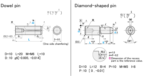
Make a hole for pin (φ10H7 depth: 10㎜) on the mount.
When using the diamond-shaped pin, please pay attention to the direction of the diamond-shaped pin. As shown below, make sure the diamond-shaped pin peak faces to the dowel pin.
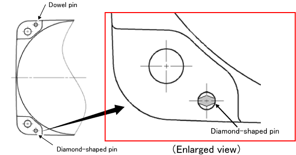
Drive the dowel pins into the mount to fix. They can minimize positional deviations when you remove and reinstall the robot unit for maintenance.
Installing the Robot on the Tilted Surface
If you install the robot on the tilted surface, you need to determine the motion angle range of J1 according to the following figure. At this time, install stoppers at 5° to 20° outside of the motion range.
J1 motion angle range according to tilted surface angle
| Model type | Tilt angle | Motion range | Model type | Tilt angle | Motion range | |
|---|---|---|---|---|---|---|
| VMB-2515 | 0° to 35° | ±170° | VMB-2518 | 0° to 30° | ±170° | |
| 35° | ±63° | |||||
| 40° | ±66° | 40° | ±52° | |||
| 45° | ±55° | 45° | ±45° | |||
| 50° | ±48° | 50° | ±41° | |||
| 55° | ±44° | 55° | ±37° | |||
| 60° | ±41° | 60° | ±35° | |||
| 65° | ±38° | 65° | ±33° | |||
| 70° | ±37° | 70° | ±31° | |||
| 75° | ±35° | 75° | ±30° | |||
| 80° | 80° | |||||
| 85° | ±34° | 85° | ±29° | |||
| 90° | 90° | |||||
| 95° | 95° | |||||
| 100° | ±35° | 100° | ±30° | |||
| 105° | 105° | |||||
| 110° | ±37° | 110° | ±31° | |||
| 115° | ±38° | 115° | ±33° | |||
| 120° | ±41° | 120° | ±35° | |||
| 125° | ±44° | 125° | ±37° | |||
| 130° | ±48° | 130° | ±41° | |||
135° |
±55° | 135° |
±45° | |||
| 140° | ±66° | 140° | ±52° | |||
| 145° to 180° | ±170° | 145° | ±63° | |||
| 150° to 180° | ±170° | |||||
| For details, refer to the graph. | For details, refer to the graph. | |||||
ID : 10541
- Related Information
- Fixing for Floor Mounting