
ID : 10724
Connectors on Robot
Overview
VLA series robot has connectors on the part A and B in the following figure.
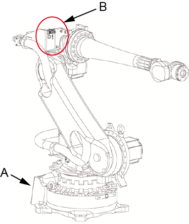
- A : Connections on robot base (distribution panel)
- B : Connections on 3rd axis (for tool)
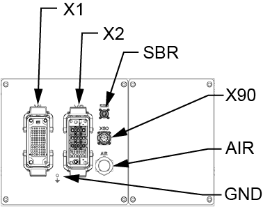
Connections on Robot Base (Distribution Panel)
The following figure shows all connections available on the robot base (distribution panel).
| Connector No. | Description |
|---|---|
| X1 | Connect with the encoder connector of the controller. |
| X2 | Connect with the motor power connector of the controller. In the robot, it is connected to the motor and brake. When using this, use the attached motor & encoder cable (required option) for wiring. |
| X90 | Connector for Hand signals. Communicate with the controller by signals (usually I/O signal) with the multibus cable. It is connected to the X200 connector on the forearm via the internal wiring. When using this, use the optional multibus cable or the attached X90 connector for wiring. |
| SBR | Connector for the brake release unit. |
| AIR | Air piping joint.
|
| GND | Screw (M6) for protective grounding conductor. |
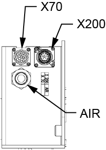
Connections on 3rd Axis (for Tool)
| Connector No. | Description |
|---|---|
| X70 | Hand I/O connector. It is connected to the X1 connector on the base via the internal wiring. When using this, use the attached X70 connector for wiring. |
| X200 | Connector for Hand signals. It is connected to the X90 connector on the base via the internal wiring. When using this, use the attached X200 connector for wiring. |
| AIR | Air piping joint.
|
Attached Connector
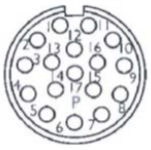
X70 Connector
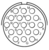
- J, T, U and V are not used.
- For pin assignment, refer to "Connector Pin Assignment".
| Connector set | Manufacturer model | Manufacturer | |
|---|---|---|---|
 |
Connector | UTO61619PH | SOURIAU |
 |
Cable gland | UTO16JCS (cable clamping range 9.5 – 14.5 mm) | |
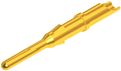 |
Connector pin | RM16M-SCD28 | |
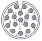
X200 Connector
- 15 and 16 are not used.
- For pin assignment, refer to "Connector Pin Assignment".
| Connector set | Manufacturer model | Manufacturer | |
|---|---|---|---|
|
Connector | ASA035N00590038000 (cable clamping range 14.0 – 17.0 mm) | TE |
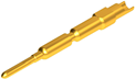 |
Connector pin | 60-0004-011-000 | |

X90 Connector
- 15 and 16 are not used.
- For pin assignment, refer to "Connector Pin Assignment".
| Connector set | Manufacturer model | Manufacturer | |
|---|---|---|---|
 |
Connector | AUA034N00480150000 (cable clamping range 7.5 – 12.0 mm) | TE |
 |
Connector pin | 61-0006-011-000 | |
Connector Pin Assignment
X1, X70 Connector
| X1 | X70 | Signal name |
|---|---|---|
| 36 | A |
+24 V |
| 12 | B |
0 V |
| - | C | GND |
| 72 | K | Output 1 |
| 71 | L | Output 2 |
| 70 | M | Output 3 |
| 69 | N | Output 4 |
| 46 | E | Output 5 |
| 47 | F | Output 6 |
| 57 | P | Input 1 |
| 58 | R | Input 2 |
| 59 | S | Input 3 |
| 60 | G | Input 4 |
| 9 | D | Input 5 |
| 21 | H | Input 6 |
| - | J | Open |
| - | T | Open |
| - | U | Open |
| - | V | Open |
X90, X200 Connector
| X90 | X200 | I/O | Fieldbus type | ||
|---|---|---|---|---|---|
| PROFIBUS | DEVICENET | PROFINET | |||
1 |
1 |
User |
Not Used | 0 Vdc | Not Used |
| 2 | 2 | User | Not Used | Not Used | Not Used |
| 3 | 3 | User | Not Used | 24 Vdc | Not Used |
| 4 | 4 | User | Not Used | Not Used | Not Used |
| 5 | 5 | User | GND | GND | GND |
| 6 | 6 | User | PROFIBUS B | Not Used | Not Used |
| 7 | 7 | User | Not Used | Not Used | TX- |
| 8 | 8 | User | Not Used | Not Used | TX+ |
| 9 | 9 | User | Not Used | Not Used | RX- |
| 10 | 10 | User | Not Used | Not Used | RX+ |
| 11 | 11 | User | PROFIBUS A | Not Used | Not Used |
| 12 | 12 | User | Not Used | Not Used | Not Used |
| 13 | 13 | User | Not Used | CAN_H | Not Used |
| 14 | 14 | User | Not Used | CAN_L | Not Used |
| 15 | 15 | Open |
Open | Open | Open |
| 16 | 16 | Open | Open | Open | Open |
| 17 | 17 | User | Not Used | Not Used | Not Used |
ID : 10724