
ID : 10951
Hardware Connection Structure
How to Connect Hardware
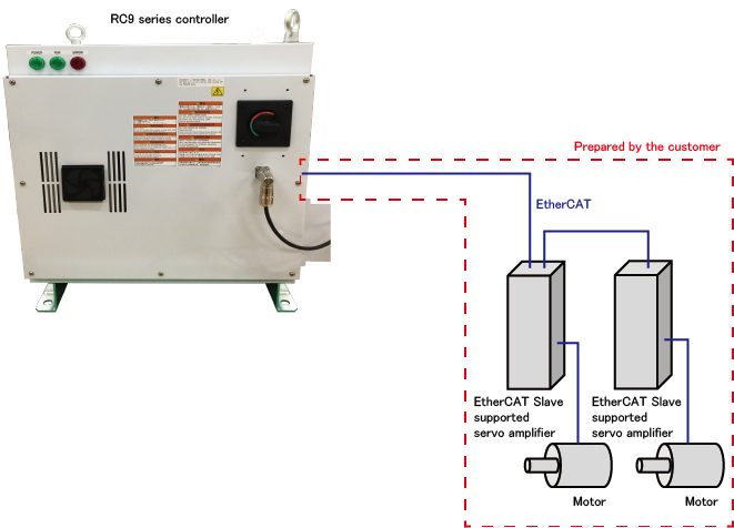
The auxiliary axis function uses EtherCAT to connect the RC9 robot controller to servo amplifiers.
The daisy chain shown below is the only applicable network topology for this function.
Do not connect the controller to anything other than a servo amplifier while the controller is connected to the daisy chain.
For connection, be sure to use a twisted pair cable rated "category 5e" or higher.
For details on how to connect them, contact our sales representatives.
If you restart the RC9 robot controller while the servo amplifier is on, the RC9 controller will output the error indicating a broken EtherCAT cable.
This occurs because the RC9 controller receives the broken EtherCAT cable error that is output by the servo amplifier at the moment when the controller is turned off.
To avoid this, turn off the servo amplifier and the RC9 controller at the same time.
In addition, turn on the servo amplifier before turning on the RC9 controller.
Servo Amplifier Compatible with the Auxiliary Axis Function
Use our designated EtherCAT Slave supported servo amplifier to configure a robot system using the auxiliary axis function.
Below is the amplifier compatible with the auxiliary axis function.
| Manufacturer | Model name | Vendor ID | Product code |
|---|---|---|---|
| SANYO DENKI CO.,LTD. | SANMOTION R 3E Model | 441 | 11 |
Even if you use a compatible amplifier, the following amplifiers and motors cannot be used.
- Multi-axis servo amplifiers
- Linear motors
- Incremental encoders
Wiring of the auxiliary axis brake
Ensure that the power source to release the brake for an auxiliary axis motor satisfies the power capacity required for the motor brake.
The recommended brake release circuit for SANMOTION R 3E Model
The following operations require wiring of the recommended brake release circuit.
- Controlling the brake through the RC9 robot controller in conjunction with the auxiliary axis motor's turning on and off.
- Controlling the brake for an auxiliary axis through the smart TP
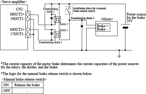
To use the recommended brake release circuit, disable the servo amplifier custom setting.
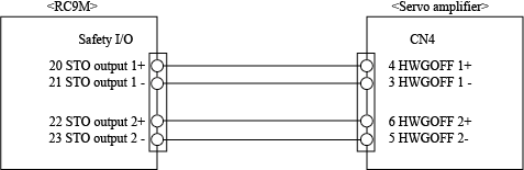
Wiring of STO Circuits
When using SANMOTION R 3E Model
To synchronize the STO signals of the robot joints and the auxiliary axis, connect the RC9 STO signal lines to the auxiliary axis amplifier as shown below.
Note the following point when synchronizing the STO signals of the robot joints and the auxiliary axis as shown above.
 is a parameter setting value of [Maximum motor rotation acceleration time (ms)] in [Path parameter setting] for the axis intended to operate, and
  is the time required from the input of a signal, such as an emergency stop signal, to the STO signal output. If is longer than , the robot suddenly stops operating by the motor brake because the STO function turns on during deceleration.
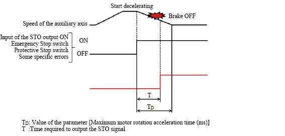
, which is the time required to output the STO signal, varies depending on the robot model.
| Robot model | The time required to output the STO signal |
|---|---|
| VMB | 600 ms |
| VLA | 1400 ms |
If you want , which is a parameter setting value of [Maximum motor rotation acceleration time (ms)] for the axis intended to operate, to be longer than , which is the time required to output the STO signal, with the timing of conducting Manual Reset for the RC9 controller being synchronized with the timing for the servo amplifier, connect the STO signal lines to a delay circuit such as an off delay timer.
Use the formula below to calculate how many seconds the delay time will be.

ID : 10951