
ID : 10973
Path Parameter Setting
This section describes how to set path parameters, which determine the auxiliary axis operation conditions such as speed, acceleration, and motion range.
Setting through WINCAPSIII
1
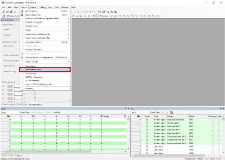
Select [Joint Setting Table] in the [Project] tab in WINCAPSIII.
2
Change path parameters in the [Joint Setting] tab on the [Joint Setting] screen.
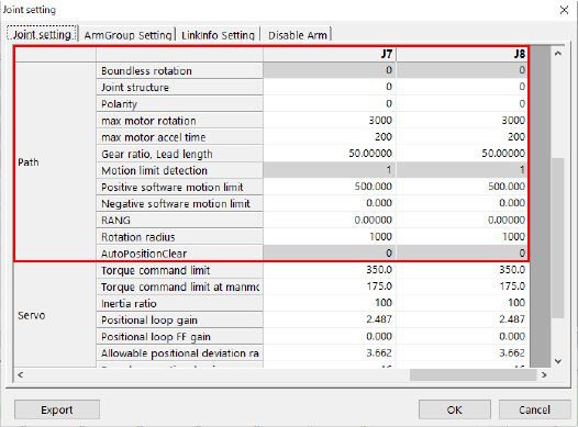
Specify the parameters you want to adjust and then press [OK].
Pressing [OK] will save the settings.
For details of each parameter, refer to the “Path parameter list” at the bottom of this page.
Setting through the Smart TP
1
Operation path: Top screen - [F2 Arm] - [F12 Maintenance] - [F10 Joint Settings]

After the [Joint Settings] screen appears, press [F4 Path Parameter].
2
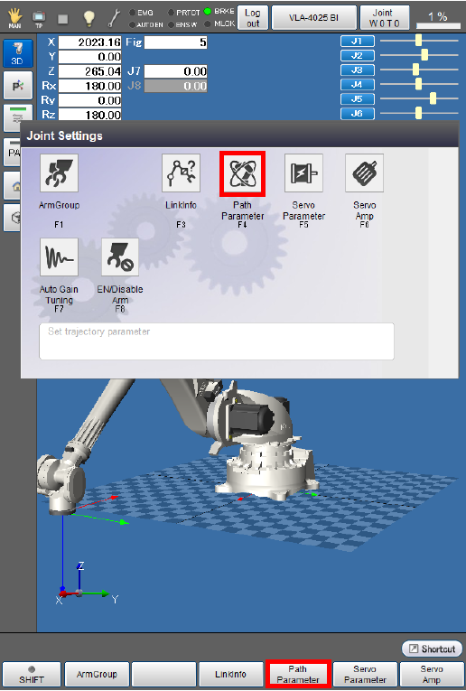
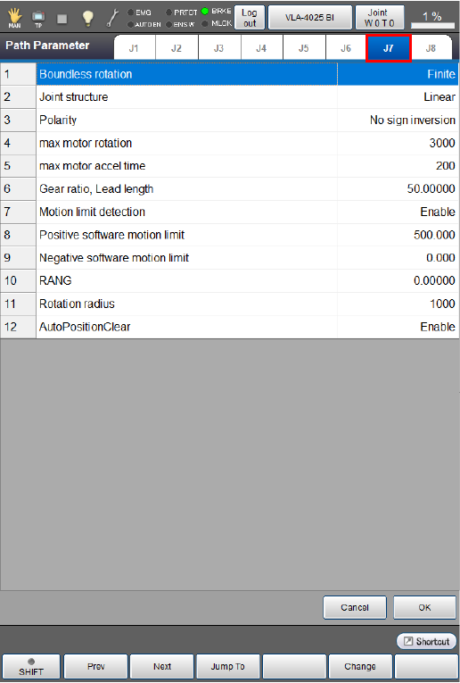
You can check and set path parameters on the window appearing after [F4 Path Parameter] is pressed.
3
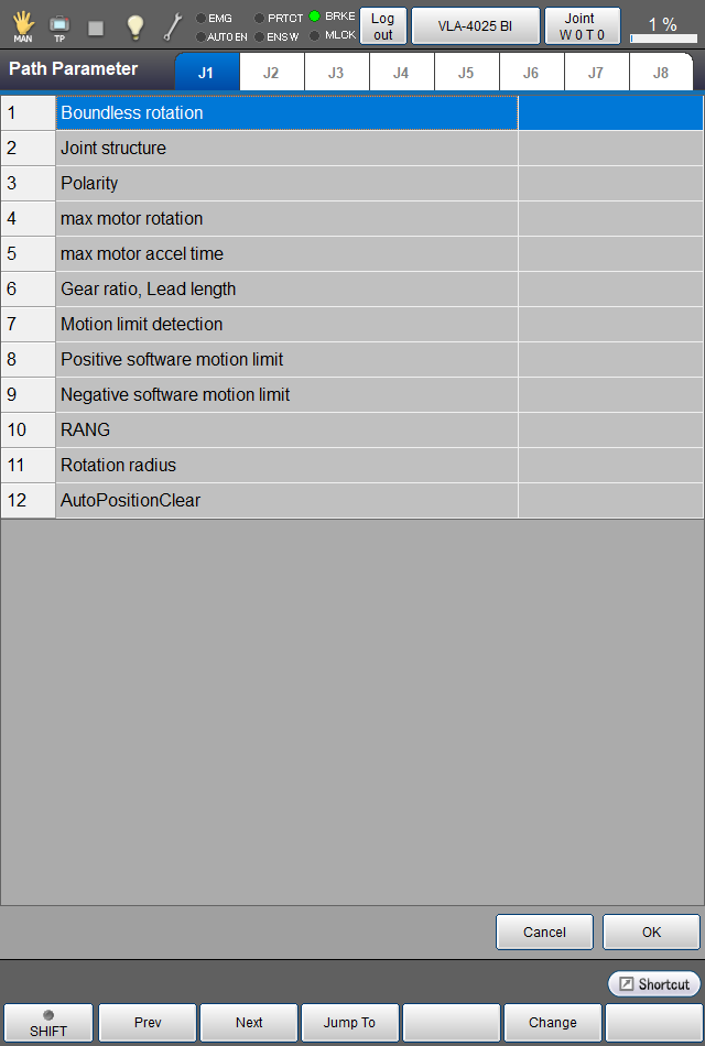
Select an axis tab for which you want to adjust the path parameters.
Adjust the setting of each path parameter, then press [OK].
For details of each parameter, refer to the “Path parameter list” at the bottom of this page.
4
After setting all the path parameters, press [OK].
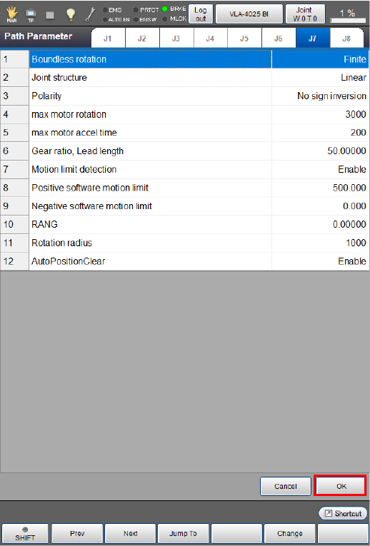
This will save the path parameter setting and take you back to the [Joint Settings] screen.
Path parameter list
| Parameter name | Entry range | Factory default | Unit | Description | Remarks |
|---|---|---|---|---|---|
|
Boundless rotation (Finite, Infinite) |
"Finite" or "Infinite" |
Finite | To rotate the motor 32768 times or more in the same direction, set this parameter to 1: Infinite. | Setting this parameter to "1: Infinite" requires the Motion limit detection parameter to be set to "0: Disabled". | |
|
Joint structure (Linear, Rotate) |
"Linear" or "Rotate" |
Linear | If your optional mechanism to be connected to the specified motor has a sliding joint, then set 0: Linear; if a rotary joint, set 1:Rotate. | ||
|
Polarity |
"0: No sign inversion" or "1: Sign inversion occurs" |
0: No sign inversion | If you want the auxiliary axis to rotate oppositely to the rotational direction in which the axis moves in the positive direction, set this parameter to "1: Sign inversion occurs". | Note that the rotational direction in which the axis moves in the positive direction varies depending on the servo amplifier maker. | |
| Max Motor rotation[rpm] |
1 to 6000 |
3000 | rpm | Set the maximum speed of the specified motor. | |
| Max Motor accel time[ms] |
1 to 100000000 |
200 | ms | Set the motor acceleration time required for the specified motor to reach the maximum speed. | |
| Gear ratio, Lead length |
0.00001 to 21474.83647 |
50.00000 | For rotary joints, set the deceleration ratio (motor rotation/joint rotation). For sliding joints, set the lead (movement) per motor rotation. | ||
|
Motion limit detection |
"Disabled" or "Enabled" | Enabled | To make the controller check the motion limit and issue an error if the specified joint is out of the range, set 1: Enabled. | Setting the Boundless rotation parameter to "1: Infinite" requires this parameter to be set to "0: Disabled". | |
| Positive software motion limit [mm],[dig] | 500 |
For rotary joints : deg For sliding joints : mm |
Set the positive motion limit. | ||
| Negative software motion limit [mm],[deg] |
-1000000 to 1000000 |
0.000 |
For rotary joints : deg For sliding joints : mm |
Set the negative motion limit. | |
| RANG[mm], [deg] |
-21474.83648 to 21474.83648 |
0.00000 |
For rotary joints : deg For sliding joints : mm |
Set the RANG value. | |
| Rotation radius[mm] |
0 to 100000 |
1000 | mm |
For rotary joints, set the maximum radius of rotation. For sliding joints, no setting is required. |
For details, see "Setting the Radius of Gyration”. |
| AutoPositionClear |
"Disabled" or "Enabled" |
Enabled |
Set whether to execute POSCLR automatically. |
(Note 1) |
Note1 : When [AutoPositionClear] is set to [Enabled], if the angle of the current position is the multiple of +360 degrees, Posclr will reset the axis to 0 degrees. However, it may set to +360 degrees due to the internal calculation error. Also, the multiple of -360 degrees may set to -360 degrees. Therefore, the motion command that has been written in immediately after Posclr may perform unexpected behavior.
ID : 10973