
ID : 10953
How to Design a Servo Mechanism
This section describes how to design the servo mechanism using the auxiliary axis function.
Example of the Mechanism
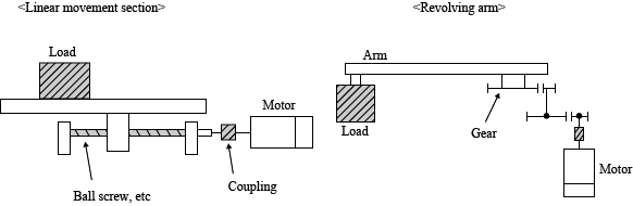
The mechanism is classified into a linear movement section and a revolving arm section as shown in the figure below.
Selection of the Drive System
An appropriate control cannot be performed if a rapid torque fluctuation occurs due to stick slip or the like. The typical examples of appropriate and inappropriate drive systems are as shown below:
| Drive System | Conditions | Adequacy |
|---|---|---|
| Ball screw | Grinding : Backlash small | A |
| Rolling : Backlash large (Control instable) | B | |
| Gear | Grinding : Accuracy grade 1 or higher : Backlash small | A |
| Cutting : Accuracy grade 3 or higher : Backlash medium | B | |
| Cutting : Accuracy grade 4 or higher : Backlash large | C | |
| Screw shaft | Friction large | C |
| Harmonic drive | Friction large (Care for selection) | B |
| Slide section bearing | Linear motion bearing | A |
| LM guide | A | |
| Slide bearing : Friction large | C | |
| Seal, packing | When the calculated torque is 20% or less of the rated motor torque. (The calculated torque mentioned here indicates the friction of the drive part that is converted into the torque value applied to the motor shaft.) | B |
| When the calculated torque is more than 20% of the rated motor torque. (The calculated torque mentioned here indicates the friction of the drive part that is converted into the torque value applied to the motor shaft.) | C |
A : Appropriate
B : This indicates the need for the careful selection of components and the possibilities of unstable system control and a system with large backlash.
C : Inappropriate
ID : 10953