
ID : 11105
Storing of the MC9 series
This section describes the process to store a controller in the controller protective box (MC9) and to connect wires.
Before operation, make sure that there is no power supply from the facilities.
The following uses the MC9 series controller as an example.
Recommended torque : M3:0.6N・m, M4:1.5N・m, M5:3N・m, M6:5N・m
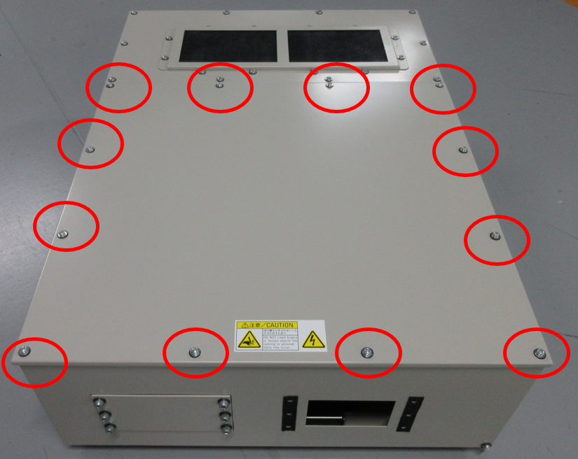
1
To remove the top panel, unscrew M4 screws (12 pieces) on the top plate B.
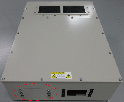
2
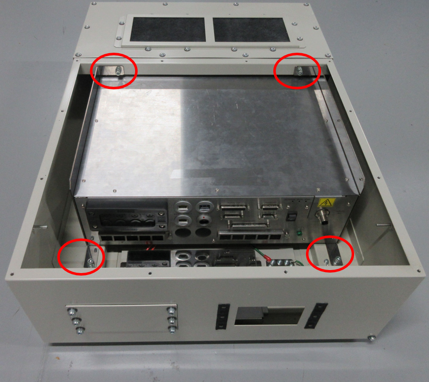
To use 11 or more cables, remove the square hole plate enclosed in the red dotted circle.
Please purchase the cable multi-outlet plate kit (option part) and install it.
- Cable multi-outlet plate kit (sold separately)
| Part name | Part number |
|---|---|
| Cable multi-outlet plate kit (MC9 controller protective box) | 414880-086* |
3
Remove the terminal board cover (metal plate), and then, remove the terminal board cover (plastic).
Lay prepared power cable on the terminal board cover as the figure shows. (M4 screw)
For the preparation of cables, see "Preparation of the power cable".
Once the power cable is laid, fix the electric wires with a cable tie, and then put the terminal board cover (plastic) and the terminal board cover (metal plate) back in place.
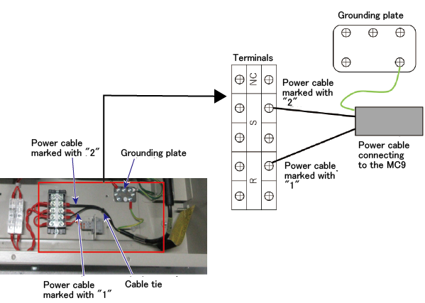
When the terminal board cover (metal plate) is put, be careful not to catch wires by the cover.
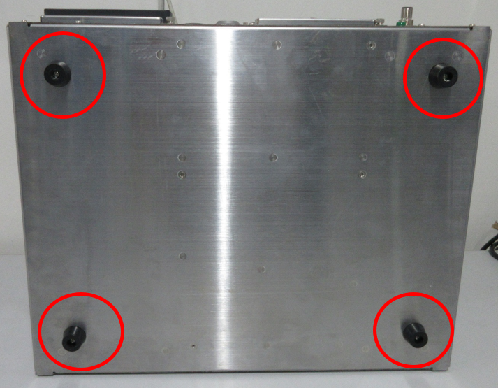
4
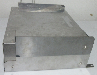
Remove the four rubber caps at the bottom of the MC9 series.
5
As the following figure shows, install the controller support bracket L on the left side of the MC9, and the controller support bracket R on the right side of the MC9, respectively.
Controller support bracket L and R are temporarily installed inside of the controller protective box (MC9) at the shipment.
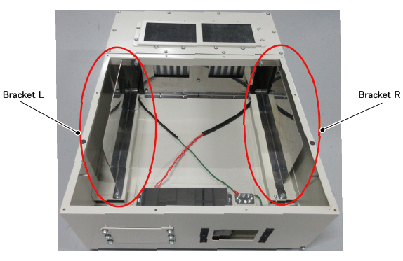
With the M5 screws that come with the controller protective box (MC9), secure it.
| Left side of the MC9 series | Right side of the MC9 series |
|---|---|
 |
 |
6
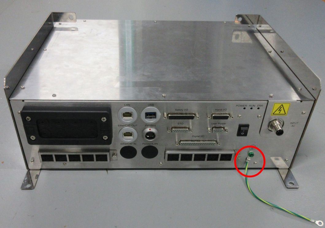
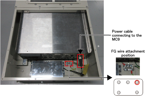
Connect the FG harness to the earthing point  , marked by red circles (solid line) in the image below.
7
As the image shows, install the MC9 series in the protective box.
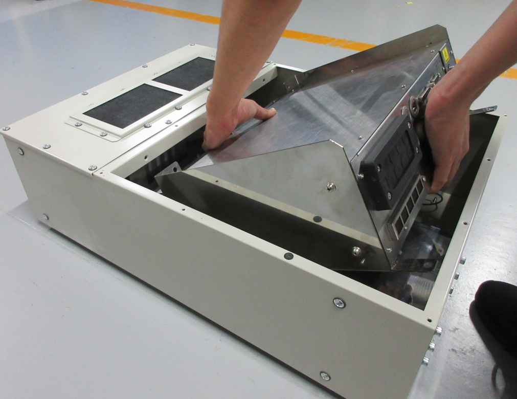
Tighten eight of mounting holes on the bracket with M6 screws.
9
Pass cables through the holes of multi-outlet plate EMS10 (accessory parts) and connect them to the MC9 series.
For information on how to attach the multi-outlet plate, see [Clamping the Cables].
10
Connect the power cable on the MC9 side to the MC9 series.
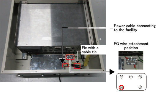
11
Connect the power cable (facility side) as the image shows, and connect the protective ground wire.
Fix the connected cables with a cable tie.
12
Put the top plate back in place with 12 of M4 screws which was removed in the STEP1.
ID : 11105