
ID : 1430
Overview
Configuration of Parallel I/O Board
Mounting a single parallel I/O board on the robot controller allows 40 points for input and 48 points for output, in addition to the Mini I/O's 16 points each for input and output.
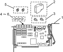
The parallel I/O board is configured as shown below.
| No. | Components | Part Number | Remarks |
|---|---|---|---|
| 1 | Parallel I/O board (including Nos. 2 through 6) |
410010-680* | NPN type, integrated in the controller |
| 410010-681* | PNP type, integrated in the controller | ||
| 410010-664* | NPN type, shipped alone | ||
| 410010-665* | PNP type, shipped alone | ||
| 2 | Mini I/O connector kit | 410159-019* | For wiring to Mini I/O (CN5) This kit consists of : - Connector (PCR-E68FS) - Connector cover (PCS-E68LPA-1E) (Both of these are manufactured by HONDA TSUSHIN KOGYO CO., LTD.) |
| 3 | Screw with washer (2 pieces) | 410815-075* | For securing the board (M3x6) (When the board is integrated at the factory, these screws are used in the controller.) |
| 4 | Fuse (4A) | 410054-025* | F3 fuse (LM40) that comes with the PNP type only |
| 5 | Fuse (1.3A) (3 pieces) | 410054-023* | For F1, F2, F4, F5, and F6 fuses (LM13) |
| 6 | Short socket (2 pieces) | 410874-037* | See "I/O power supply settings". |
|
|||
The parallel I/O board can be incorporated into any of the extension slots provided in the robot controller. (Refer to "Mounting I/O Extension Boards".)
- When turn the motor power ON after mounting the board, "Shutdown since driver installation of the new device was completed." is displayed.
Press "OK" to shutdown controller, then turn the motor power ON when "It is now safe to turn of your computer" appears on the screen.
After reboot is completed, change the Field net device and I/O assignment with WINCAPS, then send the digital I/O parameter to controller. - For safety reason and to prevent damage to the devices, disconnect the power cable of the controller or shut down the power supply to the controller from the facilities before disconnecting or connecting cables.
ID : 1430