
ID : 1433
Part Functions and Board Settings
I/O Power Supply Settings
Either an external power supply or the internal power supply can be set as the parallel I/O board's I/O power supply (+24V DC). An external power supply is the factory default setting.
I/O Power Supply Setting Method
| I/O power supply settings | P1 and JP2 settings | Setting method |
|---|---|---|
| External power supply |
JP1, JP2 (Open) |
Use the board under the factory default settings (both JP1 and JP2 are open). |
| Internal power supply |
JP1, JP2 (Short-circuit) |
Short-circuit pin 1 to 2 on each of JP1 and JP2 using a short socket. |
|
(Note) Check that the controller's power is turned OFF before setting. |
||


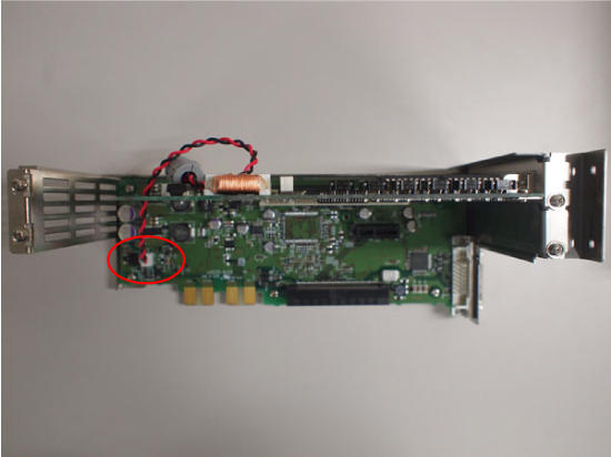
Connecting Internal Power Supply Cables When Mounting add-on Parallel I/O Boards
Disconnect the I/O power switching harness from CN2 on the parallel I/O board and connect it to 24 V connector on the controller's printed circuit board.
Fuses
The specifications of fuses F1 to F6 are listed below.
| Name | Capacity | Type (Manufacturer) | Function | Cause of fuse disconnection |
|---|---|---|---|---|
| F1 | 1.3A | LM13 (Daito Communication Apparatus) |
For internal power supply |
Output port or power supply short circuit, etc. when the internal power supply is used. |
| F2 | 1.3A | LM13 (Daito Communication Apparatus) | ||
| F3 | 4A | LM40 (Daito Communication Apparatus) | For 24V power supply | Application of excess power, reverse connection of power supply, output port short circuit, etc. |
| F4 | 1.3A | LM13 (Daito Communication Apparatus) | For signal output (I/O ports 3840 to 3855) |
Output port short circuit (I/O port 3840 – 3855) IC1 or IC2 transistor short-circuit failure, etc. |
| F5 | 1.3A | LM13 (Daito Communication Apparatus) | For signal output (I/O ports 3856 to 3871) |
Output port short circuit (I/O port 3856 – 3871) IC3 or IC4 transistor short-circuit failure, etc. |
| F6 | 1.3A | LM13 (Daito Communication Apparatus) | For signal output (I/O ports 3872 to 3887) |
Output port short-circuit (I/O port 3872 – 3887) IC5 or IC6 transistor short-circuit failure, etc. |
ID : 1433