
ID : 5212
Coordinates in 4-Axis Robots
The following three coordinates are available for the 4-Axis robot.
- Base coordinates
- Work coordiantes
- Tool coordinates
Base Coordinates in 4-Axis Robots
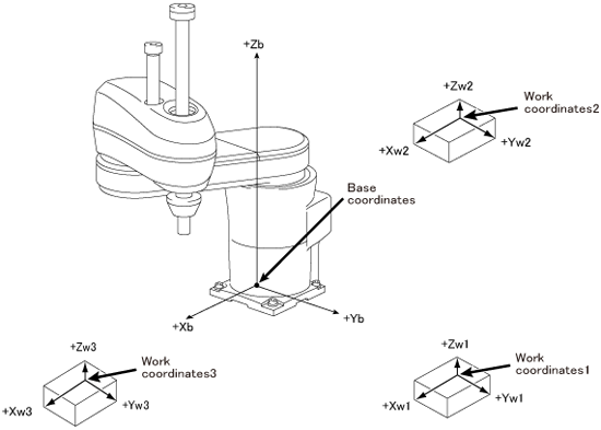
Base coordinates are 3-dimensional Cartesian coordinates with its origin at the center of the robot base. "Base" of the robot is a part where the first axis of the robot is installed.
It has components Xb, Yb, and Zb which are identical with X, Y, and Z in X-Y mode.
Work Coordinates in 4-Axis Robots
Work coordinates are 3-dimensional Cartesian coordinates defined for each operation space of workpiece. The origin can be defined anywhere and up to 7 points. Work coordinates are expressed by the coordinate origin (X, Y, Z) corresponding to the base coordinates and the angles of rotation (RX, RY, RZ) around X, Y and Z axes of base coordinates. However, value of RX and RY are defined as RX=0 and RY=0 respectively.
If work coordinates are not defined, base coordinates go into effect.
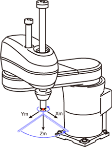
Tool Coordinates in 4-Axis Robots
A tool mounting surface at the end of the robot arm is called a mechanical interface. For 4-axis robots, two types of mechanical interfaces are available, shaft type and flange type.
In the standard specification of 4-axis robot, the mechanical interface is shaft. A flange is widely used option which facilitates to attach customer-prepared tool end.
Three-dimensional Cartesian coordinates whose origin at the center of mechanical interface are called mechanical interface coordinates.
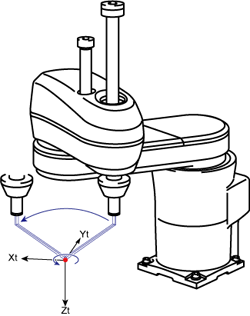
Tool coordinates are three dimensional Cartesian coordinates whose origin at the end of the tool mounted on the flange.
Based on the origin of mechanical interface coordinates, tool coordinates define the offset distance components and axis rotation angles.
Up to 63 tool coordinates can be defined and assigned tool coordinates #1 to #63.
TOOL 0 is defined as mechanical interface coordinates.
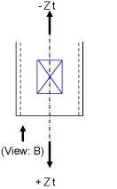
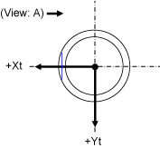
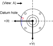
Mechanical Interface Coordinates
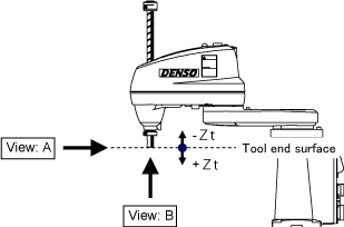
| Viewed from A | Viewed from B | |
|---|---|---|
| Shaft type (standard specification) |
 |
 |
| Flange type | 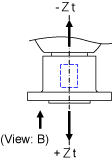 |
 |
The parameter in tool definition is as follows. Each parameter specifies tool offset on each tool coordinate. Rx and Ry shall be input 0.
| Tool components | Used for | Unit |
|---|---|---|
| X | Offset in Xt direction | ㎜ |
| Y | Offset in Yt direction | ㎜ |
| Z | Offset in Zt direction | ㎜ |
| RX | 0 | degree |
| RY | 0 | degree |
| RZ | Rotation angle in RZt direction | degree |
Advantages of Tool Coordinates in 4-Axis Robots
Using tool coordinates in Manual mode allows the tool end to move centering on the point that has been offset in the tool definition.
 |
 |
| Manual Rotation of 4th Axis in X-Y mode, without Tool Definition | Manual Rotation of 4th Axis in X-Y mode, with Tool Definition |
ID : 5212