Terminology and Definitions
- Tracking mode
-
"Tracking mode" means a state that the conveyor tracking is enabled.
Calling conveyor tracking-dedicated commands (TrackApproach, TrackDepart, and TrackMove) while the conveyor tracking is enabled will allow robots to follow the target position according to the conveyor's motion.
- Non-tracking mode (Normal operation mode)
-
"Non-tracking mode" means a state that the conveyor tracking is disabled. This is the default setting at the controller startup.
To move a robot arm to a static target position, use motion commands (such as Approach, Depart, and Move) in this mode.
Executing TrackApproach, TrackDepart, or TrackMove, all of them are conveyor tracking-dedicated commands, in this mode will issue an error.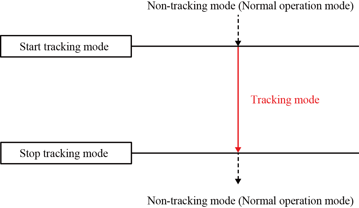
- Conveyor catch-up motion (Catch-up motion)
-
Conveyor catch-up motion indicates a robot motion that catches up to the target workpiece on the conveyor.
The robot accelerates its speed until it catches up to the workpiece, and then moves in parallel to the conveyor once the robot reaches the work piece.
- Robot task motion
-
Robot task motion is a robot motion that performs actual robot tasks along with the conveyor catch-up motion.
For example, a TrackApproach motion is a synthesized motion of the conveyor catch-up motion and Approach motion. In this context, Approach motion corresponds to the robot task motion.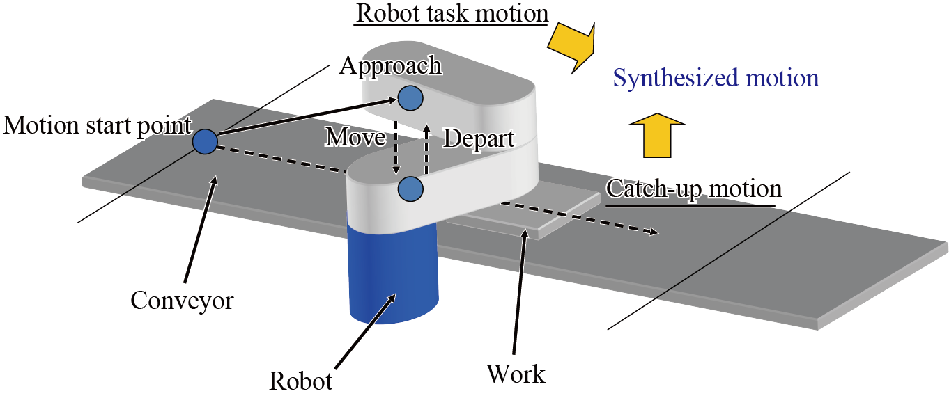
- Conveyor tracking buffer (Tracking buffer)
-
This indicates the memory storage area that is used to store data with regard to workpieces detected by a sensor or vision sensors.
The following data is stored when a workpiece is registered.Stored values (1) Index value in the tracking buffer (integer type data) (2) Conveyor encoder value at workpiece detection (integer type data) (3) Vision sensor detection coordinates (variant type data array) Sensor detection position (position type data) (4) User data (integer type data) (5) Attribute data (integer type data, or integer type data array)
- Conveyor vector
- A conveyor vector is a three-dimensional vector whose length is one. This shows the motion direction of a conveyor. This is a direction vector viewed from the base coordinate system.
- Tracking-target work
-
A tracking-target work indicates a workpiece data that just has been taken out of the tracking buffer and is about to be used for the tracking motion.
This will be the processing object of some commands, such as TrackInRange and TrackArrivalTime.
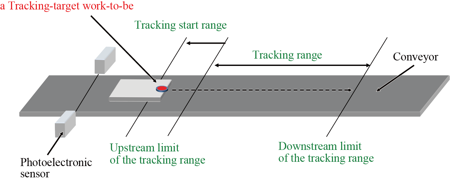
- Tracking range
-
This is an area on the conveyor where the robot can perform the conveyor catch-up motion.
Tracking range is delimited by the upstream limit and the downstream limit. The upstream limit is set to the direction where a workpiece comes from, whereas the downstream limit is set to the direction where a workpiece goes to. To use multiple robots, set a tracking range for respective robots.
- Upstream limit of the tracking range (Upstream limit)
- This is the tracking limit on the upstream of the conveyor. Once a workpiece passes this limit, a robot starts the conveyor catch-up motion.
This must be set within the motion range of the robot arm.
- Downstream limit of the tracking range (Downstream limit)
- This is the tracking limit on the downstream of the conveyor. Once a work piece reaches this limit, robot stops the conveyor catch-up motion and starts deceleration.
This must be set within the motion range of the robot arm.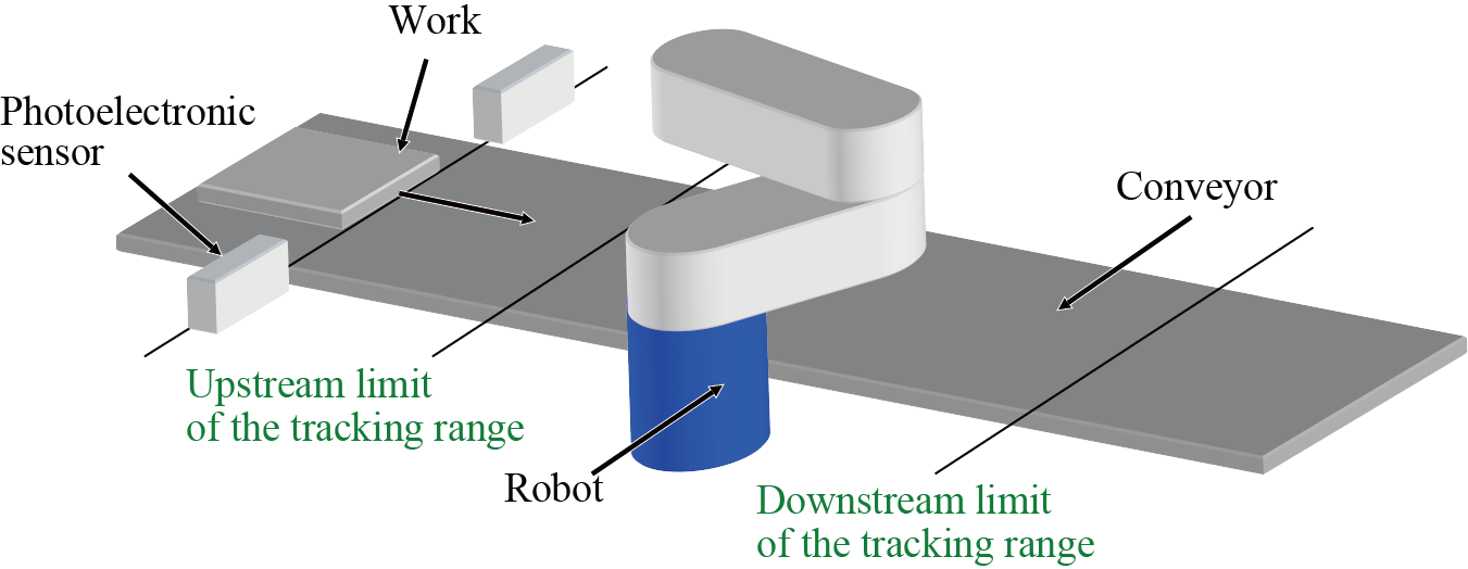
- Calibration point on upstream limit
-
This is a point registered at the conveyor calibration to delimit the upstream limit of the tracking range.
This is a center position of a robot flange viewed from the base coordinate system.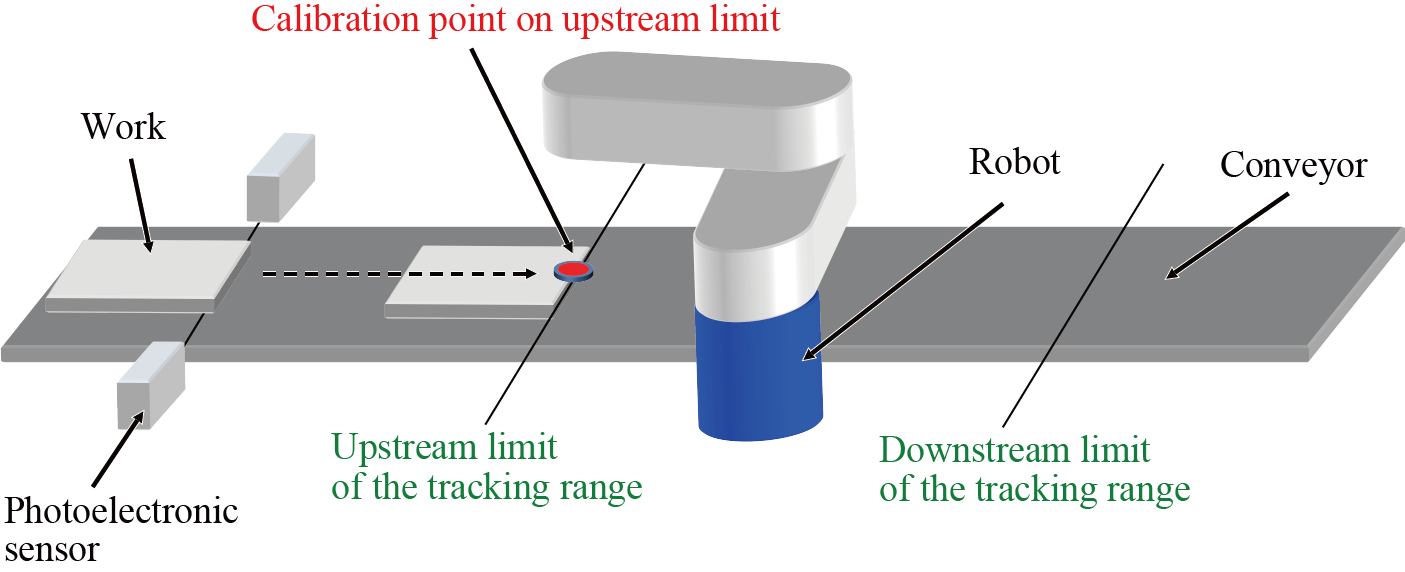
- Calibration point on downstream limit
-
This is a point registered at the conveyor calibration to delimit the downstream limit of the tracking range.
This is a center position of a robot flange viewed from the base coordinate system.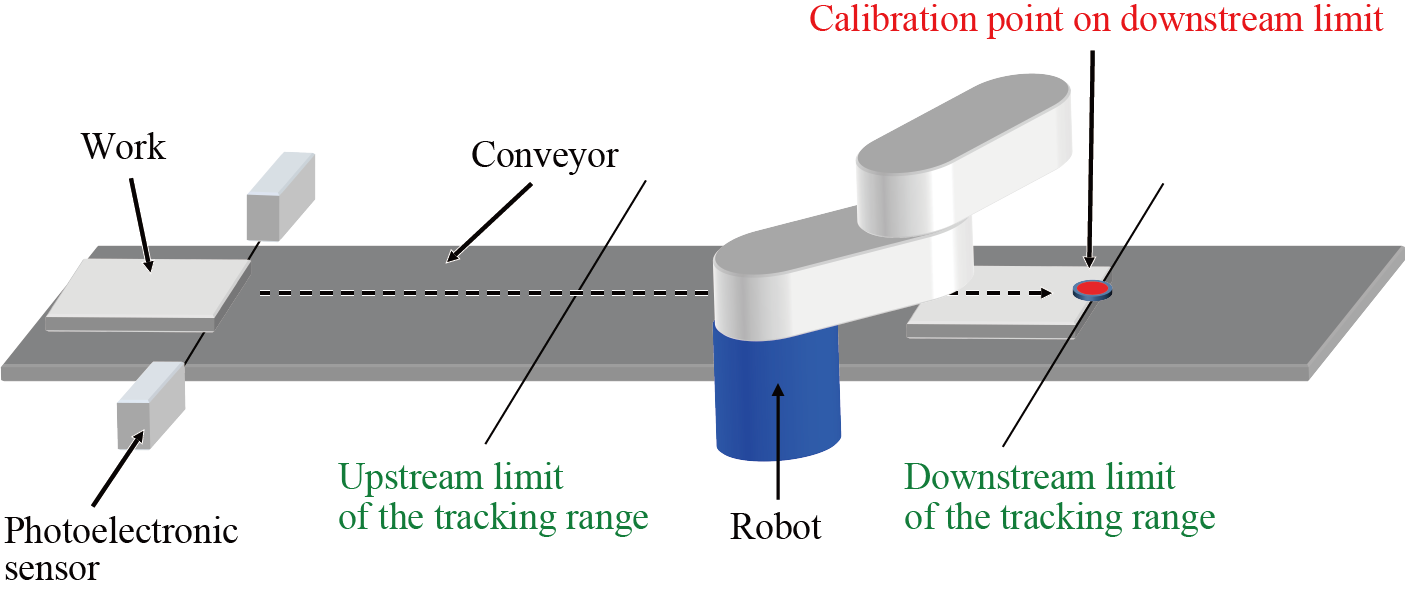
- Conveyor reference position
- This is a midpoint(X,Y,Z) between the calibration point on upstream limit and the calibration point on downstream limit.
As the calibration point on upstream and/or downstream limit changes, this position changes together.
This is a center position of a robot flange viewed from the base coordinate system.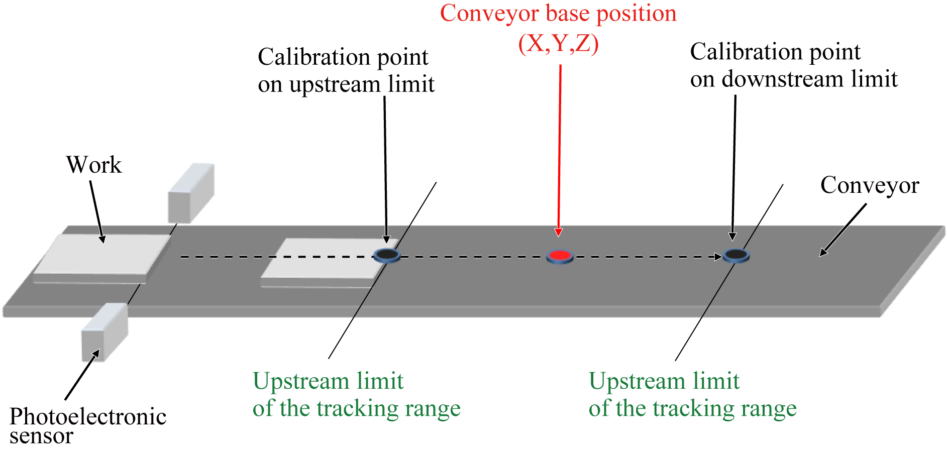
- Default posture of holding the work
- This is the posture (Rx, Ry, Rz) of position type that goes and holds a workpiece when operating the conveyor tracking.
This is registered when teaching of the upstream limit of the tracking range is executed.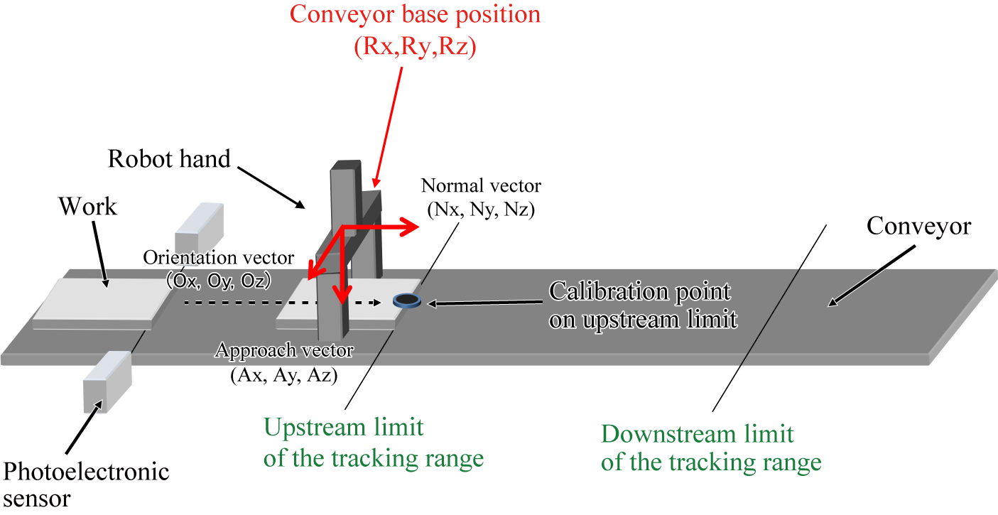
- Conveyor Base Position
- This consists of the conveyor reference position and the default posture of holding the work. It is position type data.
- Calibration
- In the conveyor tracking of RC8, calibration means measuring the exact positional relationship between the conveyor, sensor (vision sensor), and robot. Specifically, it refers to executing the conveyor calibration, sensor calibration (at the time of sensor tracking), and camera calibration (at the time of vision tracking).
- Conveyor calibration
- In the conveyor tracking of RC8, conveyor calibration means measuring the exact positional relationship between the conveyor and robot. Specifically, it means measuring the following parameters.
| Parameter name | Description |
|---|---|
| Conveyor CALDATA(X, Y) | Rotating angle around the Z axis of the base coordinate that shows the motion direction of a conveyor [rad] |
| Conveyor CALDATA(Z) | Inclination seen from the XY plane of the base coordinate that shows the motion direction of a conveyor [rad] |
| Conveyor Feed Rate | Amount of conveyor movement per one rotation of encoder [mm/rev] |
| Encoder Rotation Direction | Rotational direction of encoder when the conveyor is moved from upstream to the downstream (1: Normal, -1: Reverse) |
| Parameter name | Description |
|---|---|
| Upstream limit of the Tracking range | Once a work piece passes this limit, a robot starts the conveyor catch-up motion. [mm] |
| Downstream limit of the Tracking range | Once a work piece reaches this limit, robot stops the conveyor catch-up motion and starts deceleration. [mm] |
| Parameter name | Description |
|---|---|
| Conveyor Base Position X | Midpoint X between the calibration point on upstream limit and the calibration point on downstream limit [mm] |
| Conveyor Base Position Y | Midpoint Y between the calibration point on upstream limit and the calibration point on downstream limit [mm] |
| Conveyor Base Position Z | Midpoint Z between the calibration point on upstream limit and the calibration point on downstream limit [mm] |
- Sensor calibration
- In the conveyor tracking of RC8, sensor calibration means measuring the exact positional relationship between the sensor and robot.
Between Ver.1.11.* or lower and Ver.1.12.* or higher, different storage format is used when performing calibration.
Also, in Ver.1.11.* or lower, different storage format was used by sensor tracking and by vision tracking.
The result of calibration performed by Ver.1.12.* or higher cannot be used with a controller of Ver.1.11.* or lower.
| Parameter name | Description |
|---|---|
| Conveyor Base Position Rx | RX of default posture of holding the work [deg] |
| Conveyor Base Position Ry | RY of default posture of holding the work [deg] |
| Conveyor Base Position Rz | RZ of default posture of holding the work [deg] |
- Camera parameter
- In the conveyor tracking of RC8, camera parameter means the parameter which converts the image coordinates of vision sensor to the position seen from the base coordinates of the robot.
-
Between Ver.1.11.* or lower and Ver.1.12.* or higher, different storage format is used when performing calibration.
Also, in Ver.1.11.* or lower, different storage format was used by sensor tracking and by vision tracking.
The result of calibration performed by Ver.1.12.* or higher cannot be used with a controller of Ver.1.11.* or lower.
- Camera calibration
- In the conveyor tracking of RC8, camera calibration means measuring the exact positional relationship between the vision sensor and robot. Specifically, it means measuring the camera parameter.
- Sensor detection position
- This is the position of work, which was detected by the line sensor, seen from the coordinate system of the robot.
This position is as follows. In the sensor calibration, teaching of the position of calibration point on upstream limit is executed and moved back in the opposite of the conveyor vector direction.
This is a center position of a robot flange viewed from the base coordinate system.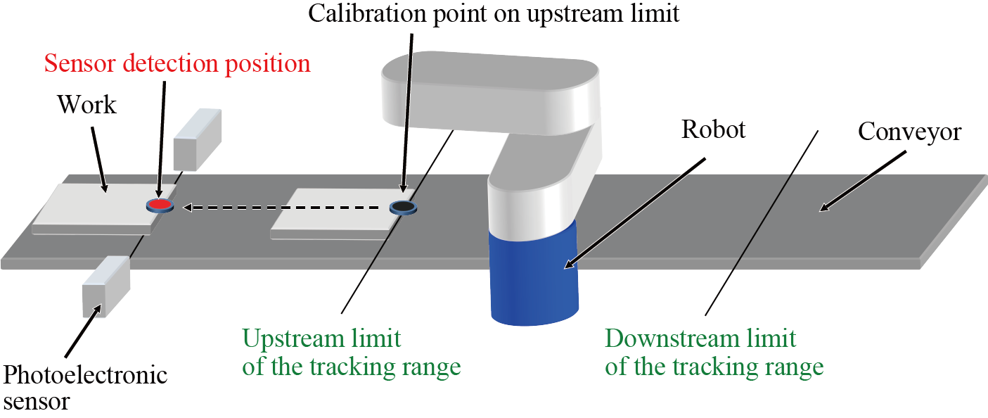
- Vision sensor detection position
- This is the position of work at the image coordinates (0, 0), which was detected by the vision sensor, seen from the coordinate system of the robot.
This position is as follows. Among the three reference points that are taught in the camera calibration, the position of the first reference point is moved back in the opposite of the conveyor vector direction.
This is a center position of a robot flange viewed from the base coordinate system.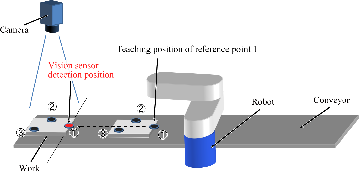
- Vision sensor detection coordinates
-
Vision sensor detection coordinates consist of image coordinates (x- and y-coordinates expressed in pixel) and workpiece's attitude angle θ(expressed in degree).
This is expressed by a variant type data array with three elements that stores x, y, and θ in this order. Each elements are expressed by single precision real type data.
- Tracking start range
-
Tracking start range is a position that the upstream limit of the tracking range is offset to the upstream direction in specified distance.
In the tracking buffer, work data that locates downstream than this range is counted as possible tracking-target work.
By setting the tracking start range, the system enables to recognize a work piece that is moved into the tracking range while the robot moves from the waiting position to the upstream limit of the tracking range, as a tracking target work.