
ID : 7890
When Using User-provided Fingers (Only Electric Gripper for COBOTTA Is Attached)
In this section, the part excluding the standard fingers from the electric gripper for COBOTTA is referred to as "standard fingers exclusion gripper".
Also, all objects which place a load on the flange (workpieces, wiring, piping, etc.), including the standard fingers exclusion gripper, are referred to as "tool-related parts".
When using the electric gripper for COBOTTA, the following four allowable ranges should be checked.
- Total Mass of Tool-related Parts
- Center of Gravity of Tool-related Parts
- Moment Applied to Driving Part of Finger
- Total Mass of Fingers
The fingers of the electric gripper for COBOTTA, which are attached at the time of factory shipment, are called "standard fingers".
Allowable Range of Total Mass of Tool-related Parts
The total mass of the tool-related parts should be within the following range of mass.
When calculating the total mass of tool-related parts, add the mass of standard fingers exclusion gripper (0.184 kg).
-
When the end-effector faces downward (within ±10 °).
Up to 0.7 kg
-
Other than above
Up to 0.5 kg
Allowable Range of Center of Gravity of Tool-related Parts
The following graph indicates the allowable range of the distance from the intersection of the rotational center axis of the 6th axis and that of the 5th axis to the center of gravity of the tool-related part, for each total mass of tool-related parts.
When calculating the total mass of tool-related parts, add the mass of standard fingers exclusion gripper (0.184 kg).
Also, when calculating the center of gravity of tool-related parts, include the standard fingers exclusion gripper in the calculation.
The center of gravity of the standard fingers exclusion gripper is located on the rotational center axis of the 6th axis, and 57.7 mm away from the rotational center of the 5th axis.
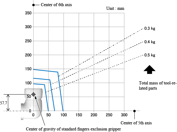
The center of gravity of the tool-related parts should be within the range indicated on the graph above.
Allowable Range of Moment Applied to Driving Part of Finger
Moment applied to the driving part of finger is determined by the total mass and the center of gravity of fingers and workpiece, and the gripping point.
The following figure indicates the values required to calculate the moment, which is applied to the driving part of finger.
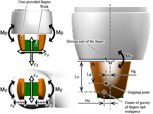
| Fz | The force in Z-axis direction applied to the finger (N) |
|---|---|
| Fy | The force in Y-axis direction applied to the finger (N) |
| Fx | The force in X-axis direction applied to the finger (N) |
| Fg | Gripping force of electric gripper for COBOTTA, which is specified when gripping (N) |
| Lg | Distance from the finger attaching surface to the gripping point (mm) |
| Hg | Distance from the center of the driving part of finger to the gripping point (mm) |
| Lc | Distance from the finger attaching surface to the center of gravity of the fingers and workpiece (mm) |
| Hg | Distance from the center of the driving part of finger to the center of gravity of the fingers and workpiece (mm) |
| Mp | Pitching moment applied to the finger (N·mm) |
| My | Yawing moment applied to the finger (N·mm) |
| Mr | Rolling moment applied to the finger (N·mm) |
Mp, My, and Mr, indicated in the figure above, should be checked if they are within the allowable range.
Also, the total of equivalent load applied to the driving part of finger ("Fz(total)" hereafter) should be calculated from the values in the figure above and checked that the value of Fz(total) is within the allowable range.
The formula for calculation of Mp, My, Mr, and Fz(total) and their allowable ranges are as follows. Make sure to stay within the allowable range indicated below.
| Formula for calculation | Maximum allowable values |
|---|---|
| Mp=(13.0+Lc)×Fy+7.5×Fz+(13.0+Lg)×Fg×1.5 | 1600 (N·mm) |
| My=(13.5+Hc)×Fy+7.5×Fx+(13.5+Hg)×Fg×1.5 | 1300 (N·mm) |
| Mr=(13.5+Hc)×Fz+(13.0+Lc)×Fx | 2000 (N·mm) |
| Fz(total)=Fz+1.19×Fx+0.38×Mr+0.48×Mp+0.58×My | 770 (N) |
A figure showing the area of the gripping points, which do not exceed the allowable values indicated above, in reality, is indicated in "Range of Gripping Points" described later. Please refer to it as well.
For the dimensional drawing of finger, refer to "Dimensional Installation Drawing of Fingers".
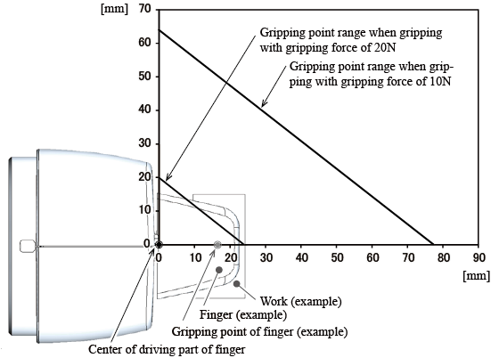
Range of Gripping Points
The following figure shows the range of distances from the center of driving part of finger to the gripping point.
To maintain the four allowable ranges indicated above, the gripping point needs to be located in the area indicated in the figure below.
In reality, the important point is not to exceed the four allowable ranges indicated above. Use the following figure just for the reference purposes, to understand how much the position of gripping point can be moved away from the center of driving part of finger.
Allowable Range of Total Mass of Fingers
An overweight finger increases the impact force in gripping a workpiece, which may cause the gripper to break. Design the finger so that its total mass does not exceed 16 g.
ID : 7890