
ID : 2642
Wire Connection Required to Prepare a Robot and RC8A (Safety-I/O-Less Controller)
This section shows the minimum wire connection required for the stand-alone robot unit to turn the motor power ON or run in Auto or Manual mode during adjustment in starting up the robot system.
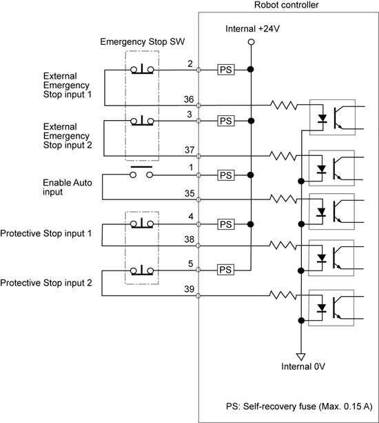
Configuration of Emergency Stop Circuitry
The External Emergency Stop and Enable Auto input signals are important for safety. Be sure to configure their circuits with contacts as shown below.
 |
Wire Connection Required for Motor ON
Short-circuiting both the Emergency Stop input circuits (dual line) only enables the motor to turn ON.
| Input signal name | Terminal number |
|---|---|
| External Emergency Stop 1 | #2 and #36 on connector CN5 |
| External Emergency Stop 2 | #3 and #37 on connector CN5 |
The different status between two emergency stop circuits, if kept for at least approx. one second, will be interpreted as an occurrence of trouble, triggering an error "One of the external emergency stop
line is disconnected."
Wire Connection Required for Automatic Operation
- Turning this signal ON (shorting) enables switching to Auto mode.
- Turning this signal OFF (opening) enables switching to Manual or Teach check mode.
| Input signal name | Terminal number |
|---|---|
| Enable Auto | #1 and #35 on connector CN5 |
| Protective Stop 1 | #4 and #38 on Mini I/O connector |
| Protective Stop 2 | #5 and #39 on Mini I/O connector |
If no Protective Stop input signals are needed, their circuits can be always short-circuited by terminal connection with jumpers between #4 and #38 and between terminals #5 and #39 on Mini I/O connector.
ID : 2642