
ID : 5423
Precautions When Designing the End-effectors
Design an end-effector such that it is in compliance with items (1) to (3) described below.
If the end-effector design precautions are not observed, the clamped parts of the robot unit may become loose, rattle or be out of position. In the worst case, the mechanical parts of the robot and robot controller may become damaged.
Mass of End-effector
Design the end-effector so that the total mass of the end-effector (including workpiece) will be lighter than the maximum payload capacity of the robot. The total mass includes the wiring, piping, etc.
Maximum total mass of end-effector (including workpiece) ≤ Maximum payload capacity (7 kg) *1
*1: If the payload exceeds 6 kg, the robot unit must be used with the flange facing down at ±45 degrees from vertical.
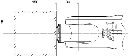
Center of Gravity Position of End-effector
Design an end-effector so that the center of gravity position of the end-effector (including workpiece) is within the range shown in Figure below.
 |
Moment of Inertia Around J4, J5 and J6
Design an end-effector so that its moments of inertia around J4, J5 and J6 (including workpiece) do not exceed the maximum allowable moment of inertia of the robot.
Moment of inertia around J4, J5 and J6 of end-effector (incl. mass of workpiece) ≤ Max. allowable moment of inertia
| Mass of payload |
Max allowable moment of inartia (kgm2) |
|
|---|---|---|
| (kg) | Around J4 & J5 | Around J6 |
| ~1 | 0.059 | 0.009 |
| ~2 | 0.118 | 0.018 |
| ~3 | 0.177 | 0.027 |
| ~4 | 0.236 | 0.036 |
| ~5 | 0.295 | 0.045 |
| ~6 | 0.354 | 0.054 |
| ~7 | 0.413 | 0.063 |
Precautions on End-effector installation
Do not apply any external force (such as hammering) on the datum hole φ5H7. Doing so will damage the hole. The diagram of "datum hole" is added.
For the datum hole, refer to "Mounting the CALSET Jig on the 6th Axis ".
ID : 5423
- Related Information
- Moment-of-Inertia Formulas