ID : 5630
Changing the Mechanical End of Y Axis and Z Axis
Restriction of Motion of Y Axis or Z Axis
The motion of the Y axis or Z axis can be restricted by supplying and installing mechanical stopper bolts.
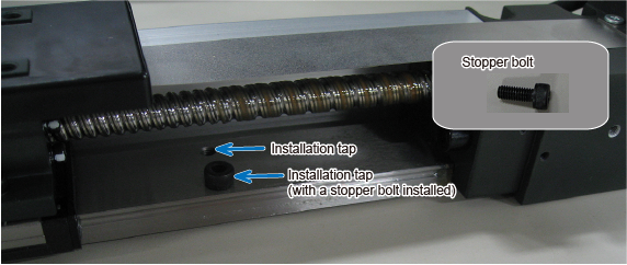
Install mechanical stopper bolts on the installation taps inside the linear module. Refer to Installation of Mechanical Stopper Bolts shown below to set an appropriate motion range.
Installation of Mechanical Stopper Bolts
1
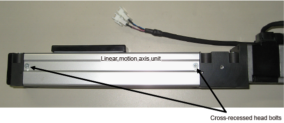
Remove the two cross-recessed head bolts on the side of the axis unit

2
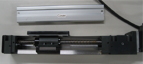
Remove the cover on the side of the axis unit.

3
Install mechanical stopper bolts on the installation taps inside.
| Target axis | Bolt | Q'ty | Bolt strength | Tightening torque |
|---|---|---|---|---|
| Z axis on LZNN or LZZN | M4×8 | 2 | 12.9 | 3.9 ± 0.8 N・m |
Y axis on all robot types Z axis on LZS* |
M5×8 | 2 | 12.9 | 8.8 ± 1.8 N・m |

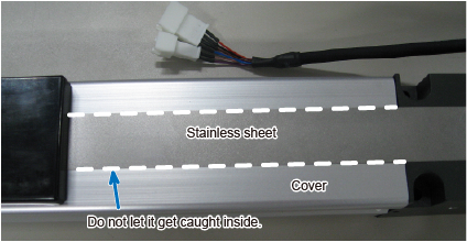
When installing the cover, be careful not to let the stainless sheet on the upper surface of the body caught inside.
The edges of the stainless sheet are sharp. Be very careful not to injure hands, etc.

4
Using the same procedure described in STEP 1 to 3, remove the cover on the other side and install two stopper bolts in total.
This is the end of the mechanical stopper bolt installation.
ID : 5630

