
ID : 5469
Parameter Setting
Details of the parameter settings are shown below.
- Set the parameter for each force control number (the parameter table number for the compliance function), as well as the control mode setting for each force control number.
- However, if the function cannot be used with just those values, then also set the values listed under "Other Parameters" according to need.
- A word written in [ ] on the Item corresponds to a Guaranteed entry on ForceParam.
- In the tables below, cells with "A" in "with" column on "Force sensor" indicates that the "Compliance Function with Force Sensor" uses the stated parameter.
- In the tables below, cells with "B" in "w/o" column on "Force sensor" indicates that the "Compliance Function" without force sensor uses the stated parameter.
- Specifying excessive control force, small inertia, viscosity or spring value will cause a high speed operation of the robot. If the robot contacts with workpieces while high-speed operation, it will damage the force sensor and robot due to the excessive collision force.
For safety reason, at the beginning of the adjustment, use the default values for spring, damp and mass, and then gradually decrease each values. For the control rate, start from the smallest value, and then gradually increase the value. Set "0%" to the direction that the force direction is not required. - For motion with constant-force pressure or fittings, you only need to adjust the viscosity parameter. Other parameters can be used as is. If you increase the viscosity, an error may occur at the force control start. In this case, increase the inertia parameter value.
- When adjustment, set the Control force and Control rate first. Refer to "Adjustment Procedure" for about adjustment procedure.
Required Settings
Operation path : Top screen - [F2 Arm] - [F2 Force Control] - [F6 Setting]
Select the force control number (the parameter table number for the compliance function) from 1 through 10, and then press [OK].
| Item Name | Units | Range | Force sensor | Details | |
|---|---|---|---|---|---|
| with | w/o | ||||
| Control mode | - | 0,1 | A | B | Select a control mode. 0: Compliance 1: Compliance with sensor |
| Control coordinate [Coordinates] |
- | 0,1,2 | A | B | Select one of the following coordinates. 0: Base coordinates 1: Tool coordinates 2: Work coordinates |
| Control force [force] (X,Y,Z,RX,RY,RZ) |
N | -5000 to 5000 | A | B |
Required to control the robot. This value specifies the limit of force to be output. |
| Nm | -1000 to 1000 | ||||
Other Parameters (Set as Required)
Operation path : Top screen - [F2 Arm] - [F2 Force Control]- [F12 Detail setting]
Select the force control number (the parameter table number for the compliance function) from 1 through 10, and then press [OK].
Only parameters used are displayed, according to the setting of the control mode described above.
| Item Name | Units | Range | Force sensor | Details | |
|---|---|---|---|---|---|
| with | w/o | ||||
| Virtual mass [Mass=Inertia] (X,Y,Z,RX,RY,RZ) |
% | 0 to 100 | A | Set the friction ratio (inertia ratio) which increases according to the acceleration. Decreasing the value will accelerate the motion speed. |
|
| Virtual damper [Damp=Damping] (X,Y,Z,RX,RY,RZ) |
% | 0 to 100 | A | B | Set the rate of resistive force, which increases according to speed. Setting a small value here will allow faster movement. |
| Virtual spring [Spring=Compliance] (X,Y,Z,RX,RY,RZ) |
% | 0 to 100 | A | B | Set the rate of return force strength, which increases according to position. Setting a small value here will allow greater movement with less force. |
| Force offset [OffSet=Offset Value] (X,Y,Z,RX,RY,RZ) |
N | -100 to 100 | B | Set the force value required to lead the robot in a specified direction. Note: Some motions may have a possibility that the robot moves unintended direction. |
|
| Nm | -100 to 100 | ||||
| Position error allowance [PosEralw=allowable position deviation] (X,Y,Z,RX,RY,RZ) |
mm | 0 to 1000 |
A | B | Set the allowable deviation value for the arm end position. If the control mode is [1: Compliance function with force sensor], the travel distance of the tool end from the force control start is monitored. |
| deg | 0 to 360 | ||||
| Joint error allowance [Eralw=allowable axis deviation] (J1 to J8) |
deg | 0 to 1000 | A | B | Set the allowable deviation value of each axis. |
| Jiont current limit [CurLmt=current limit value] (J1 to J8) |
% | 0 to 100 | B | Set the torque value (current value) of each axis. The nominal value is 100[%]. As this value decreases, the torque value (current value) reduces; as a result, the resistance will reduce. This item is not available to extended-joints (J7 and J8) even if you enter any values. |
|
| Control rate [Rate=Allowable Axis Deviation] (X,Y,Z,RX,RY,RZ) |
% | 0 to 100 | A | Set the control rate of the force sensor when the compliance function with force sensor is used. For the direction to control the force in normal use, set 100%. For the direction not to control, set 0%. |
|
| Max speed [SpMax=maximum translation speed] |
mm/s | 0 to 10000 | A | Set the maximum speed until contact. This is not used in the compliance function without force sensor. |
|
| Maximum rotation speed [RSpMax=maximum rotation speed] |
deg/s | 0 to 10000 | A | Set the maximum rotation speed until contact. This is not used in the compliance function without force sensor. |
|
Parameters Requiring Log-In Status of Maintainer
If your log-in status is Maintainer, you can configure the following items in addition to the items on the table above.
| Item Name | Units | Range | Force sensor | Details | |
|---|---|---|---|---|---|
| with | w/o | ||||
| Opt mode | - | 0,8 | A | Set the control conditions specific to the force-control operation. 0:Disable 8:Resume speed limits |
|
| impedance control virtual mass (X,Y,Z,RX,RY,RZ) |
N,kgcmˆ2 | - | A | Set a reference value of Virtual mass, mentioned above. This value corresponds to 100% of the Virtual mass. |
|
| impedance control virtual damper (X,Y,Z,RX,RY,RZ) |
Ns/m,Ncms/rad | - | A | Set a reference value of Virtual damper, mentioned above. This value corresponds to 100% of the Virtual damper. |
|
| impedance control virtual spring (X,Y,Z,RX,RY,RZ) |
N/m,Ncm/rad | - | A | Set a reference value of Virtual spring, mentioned above. This value corresponds to 100% of the Virtual spring. |
|
Parameter Requiring a Setting with WINCAPSIII
The following items can be set with WINCAPSIII only.
| Item Name | Units | Range | Force sensor | Details | |
|---|---|---|---|---|---|
| with | w/o | ||||
| Phase Shift Time (X,Y,Z,RX,RY,RZ) |
sec | 0~ | A | Set a Phase Shift Time. If vibrations are large in some speed, increase the value of this parameter from the default gradually. If vibrations became larger because of that value of parameter, decrease the value of parameter. |
|
Speed Limit
When the Compliance function with Force Sensor is used, robot speed is limited at the start of the force control in order to absorb the shock at the contact with an object. Once the robot contacts an object, the speed limit is released but the force control will keep effective without speed limit.
The robot motion speed during the speed limit is regulated to less than the setting value of "Max speed" or "Maximum rotation speed".
"Max speed" and "Maximum rotation speed" are mentioned in the above "Other Parameters".
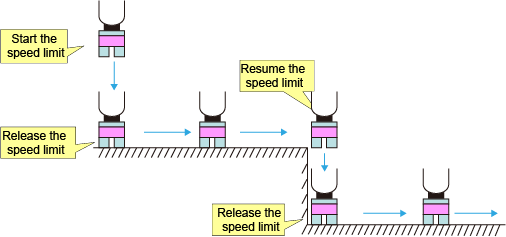
Resumption of Speed Limit
If "Opt mode" parameter is set to "Resume speed limits", the speed limit resumes once a robot moves apart from an object.
This mechanism will reduce the shock at the second time's contact with a target object in the following operation process ; The robot once moves away from the object while the Force Control is enabled, and then contacts the object again. (See the figure below)
ID : 5469