
ID : 10209
Digital I/O Wiring
This section describes the details of the Digital I/O in the following categories.
Wiring Table
From the functional point of view, I/Os on the robot controller are classified into Safety I/O, system I/O, user I/O, and internal I/O.
Among that, a system I/O equips several signals with different functions. The combination of these signals has been determined beforehand. There are two types of combination (allocations) and the I/O wiring diagram differs depending on the combination type. For details, refer to the following link.
|
Item (link destination) |
Outline |
|---|---|
| I/O Wiring Diagram for Mini I/O Dedicated Allocation | Mini I/O dedicated allocation is allocation for a field network slave terminal-unused application. The link destination contains the I/O wiring diagram of Mini I/O dedicated allocation. |
| I/O Wiring Diagram for the Standard Allocation | Standard allocation is allocation for a field network slave terminal-used application. The link destination contains the I/O wiring diagram of standard allocation. |
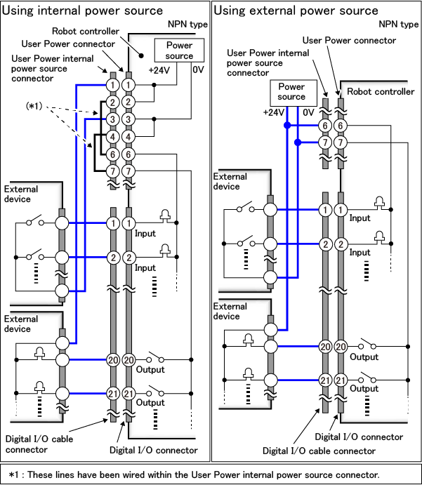
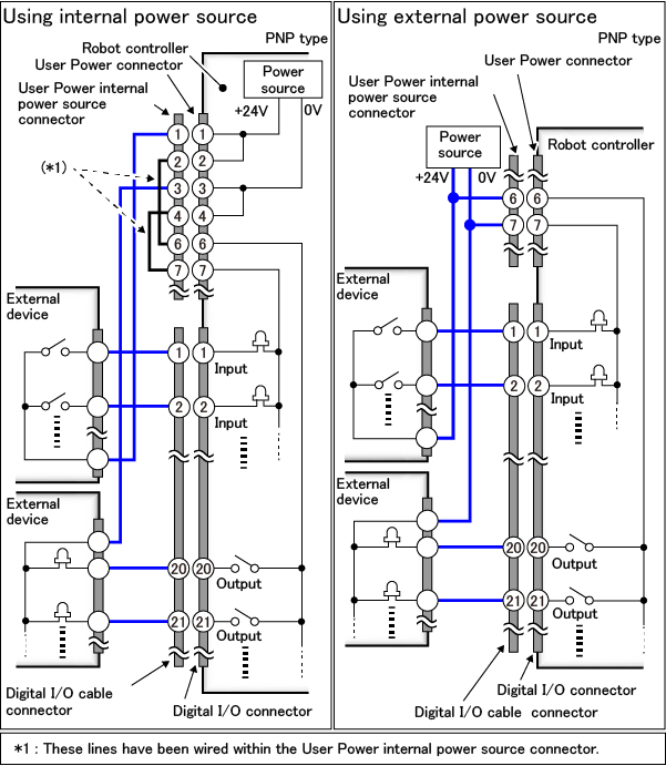
Circuit Diagram
To use a Digital I/O, you need to wire the User Power connector beforehand.
The following figure shows the circuit diagram, including the wiring of the User Power connector.
For details about the User Power connector, click here.
Circuit Diagram for NPN Type
Circuit Diagram for PNP Type
ID : 10209