
ID : 10638
Fixing the Robot Unit
This section describes the following items.
Fixing Method
It is not expected to fix the robot directly to the floor. The mount or robot fixing plate must be installed between the robot mounting surface and the concrete surface.
Stress Applied to the Robot Mount
The following drawing shows the position of each hole when the robot base part is viewed from the above.
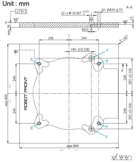
A: Holes for dowel pins
B: Holes for robot fixing bolts
Robot Fixing Bolts and Dowel pins
To fix the robot, use dowel pins and fixing bolts.
You can use robot fixing bolts and dowel pins which are shipped with the robot.
Dimension and fixing method of each bolt and pin are as shown in the following drawings.
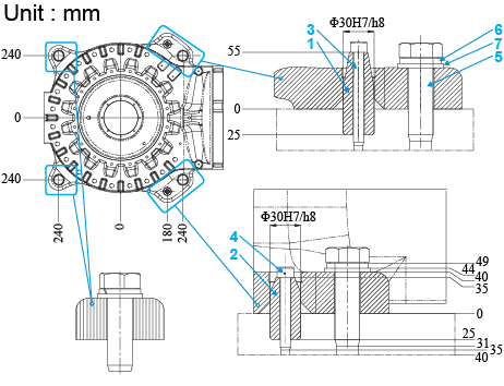
- Dowel pin ø=30mm L=80mm (quantity : 1)
- Dowel pin ø=30mm L=60mm (quantity : 1)
- Hexagon socket head bolt M10x90mm (quantity : 1)
- Hexagon socket head bolt M10x70mm (quantity : 1)
- Hexagon head bolt M24x80mm (quantity : 4)
- Spring washer ø=24mm (quantity : 4)
- Flat washer ø=24mm (quantity : 4)
Fixing Procedure
1
Clean the plate on which the robot will be placed.
2
Place two dowel pins on the plate and tighten the corresponding fixing bolts up to 50 Nm.
3
Lift the robot as described in "Transporting the Robot Unit".
4
Place the robot referring to dowel pins on the plate. Place the robot with setting the front side in the proper position. Carry out the procedure carefully in order not to damage two dowel pins.
5
Place the spring washer and flat washer and tighten four fixing bolts with tightening torque 690 Nm.
Motion Range of Axis 1 in the Angle Mount
When installing the robot on the inclined plane (max. allowable inclination 45°), it is necessary to limit the 1st axis motion range according to the following diagram.
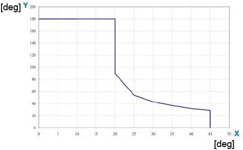
Y: Inclination angle of robot fixing surface [deg]
X: 1st axis motion range [deg]
| Tilt angle | Motion range |
|---|---|
| 20° | ±90° |
| 25° | ±54° |
| 30° | ±43° |
| 40° | ±32° |
| 45° | ±29° |
ID : 10638
- Related Information
- Fixing for Floor Mounting