
ID : 10800
Create Monitoring Models
Create a monitoring model with Arm modeling of WINCAPSIII, and then output the data to the controller.
Modeling Procedure
1
Create a model with "simple modeling" of WINCAPSIII.
If you create a monitoring model, there are restrictions depending on monitoring models. For details, refer to "Restrictions for Creating Monitoring Models".
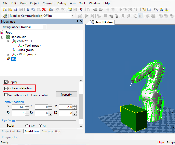
2
Select a target object, and then select the check box of "Collision detection".
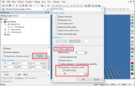
3
Click [Property] to open the [Model Setting] window. Select the Virtual fence check box.
Select the "On / Off control" check box, and select a target model ID (0 to 999) in the ID box. This will allow to enable / disable the monitoring from the VirtualFence command.
Selecting the check box of Display detection area will display the monitoring models.
Collision detection for robot is always enabled.
4
Select the detection level.
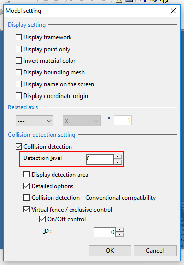
Selecting high level will realize precise monitoring though; if too high level is selected, processing time will take long, leading to the process time delay error.
5
Perform STEP2 to STEP4 for all models to be monitored.
6
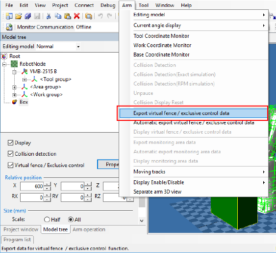
Convert virtual fence data that has just created from STEP 1 to 5 to controller-processable format, and then save it. If you want to check the exported virtual fence data, you can check it by selecting [Display virtual fence / exclusive control data].
Operation path : [Menu] - [Arm] - [Export virtual fence / exclusive control data]
Executing [Export virtual fence / exclusive control data] may cause the robot to interfere with an equipment model. In this case, uncheck [Collision detection] and [Virtual fence / exclusive control] for the equipment model, then execute [Export virtual fence / exclusive control data] again to free the robot from the interference.
After freeing the robot, reselect the check boxes of [Collision detection] and [Virtual fence / exclusive control], then execute [Export virtual fence / exclusive control data] to enable the virtual fence monitoring again.
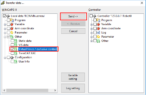
7
Send the data to the controller.
For information on how to establish communication between WINCAPSIII and robot controller, please refer to "Communication Setting" and "Data Transfer" in "WINCAPSIII GUIDE".
Reboot the robot controller after sending the data.
-
To perform this step, the robot controller and WINCAPSIII must be connected with a cable.
For information on how to connect, please refer to "Link with Robot Controller" in "WINCAPSIII GUIDE". - When you select the check box of "Arm model", you can send the creation source model data of virtual fence / exclusive control data to the controller. However, if the storage area is insufficient in the controller, the item "Arm model" will not be displayed.
8
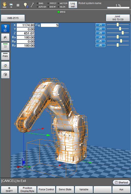
With a smart TP, open the Arm window.
To display a monitoring model, from the Arm Display Setting window, set desired objects (Arm, Tool, Work, and Area) to "Display", from the Virtual Fence Setting window, set "366: Virtual fence setting" to "1: Enable", and then reboot the controller.
Robot models are colored orange, always-monitored models are colored light orange, and models which monitoring state can be changed are colored green (when the monitoring is enabled).
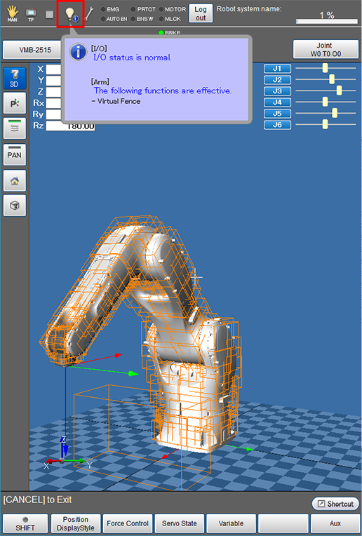
If the Virtual fence is enabled, the [I/O status/Arm status] icon on the status bar will be changed to the following figure. Tapping the icon will display the detailed information of the icon.
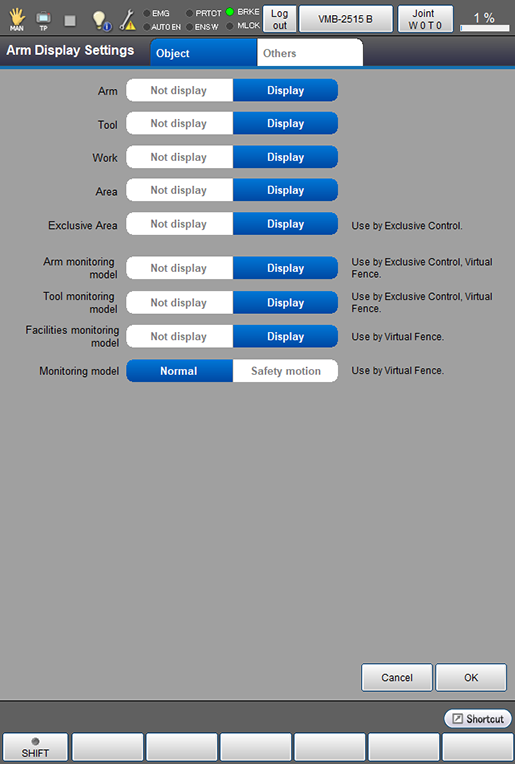
Display / Hide the Monitoring Models
Monitoring models are displayed/hidden by the following entry.
Operation path : Basic window - [F2:Arm] - [F6:Aux] - [F7:DisplaySettings]
Select [Display] or [Not display], and then press [OK].
ID : 10800