
ID : 10972
Servo Amp Parameter Setting
This section describes how to set servo amp parameters for a servo amplifier that is connected to the RC9 controller.
Setting through WINCAPSIII
1
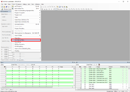
Select [Joint Setting Table] in the [Project] tab in WINCAPSIII.
2
Adjust servo amp parameters in the [Joint Setting] tab on the [Joint Setting] screen.
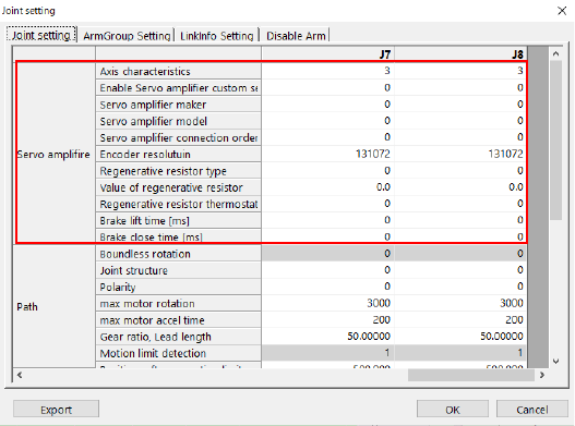
Specify the parameters you want to adjust and then press [OK].
Pressing [OK] will save the settings.
The seven parameters in the table below are not adjustable through the smart TP.
Set these parameters through WINCAPSIII.
| Item | Parameter name |
|---|---|
| Servo amplifier | Enable Servo amplifier custom setting |
| Servo amplifier maker | |
| Servo amplifier model | |
| Servo amplifier connection order | |
| Regenerative resistor type | |
| Value of regenerative resistor | |
| Regenerative resistor thermostat input port | |
| Brake lift time | |
| Brake close time |
For details of each parameter, refer to the “Servo Amp Parameter List” at the bottom of this page.
Setting through the Smart TP
1
Operation path: Top screen - [F2 Arm] - [F12 Maintenance] - [F10 Joint Settings]
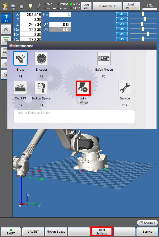
After the [Joint Settings] window appears, press [F6 Servo Amp].
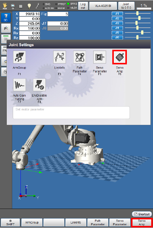
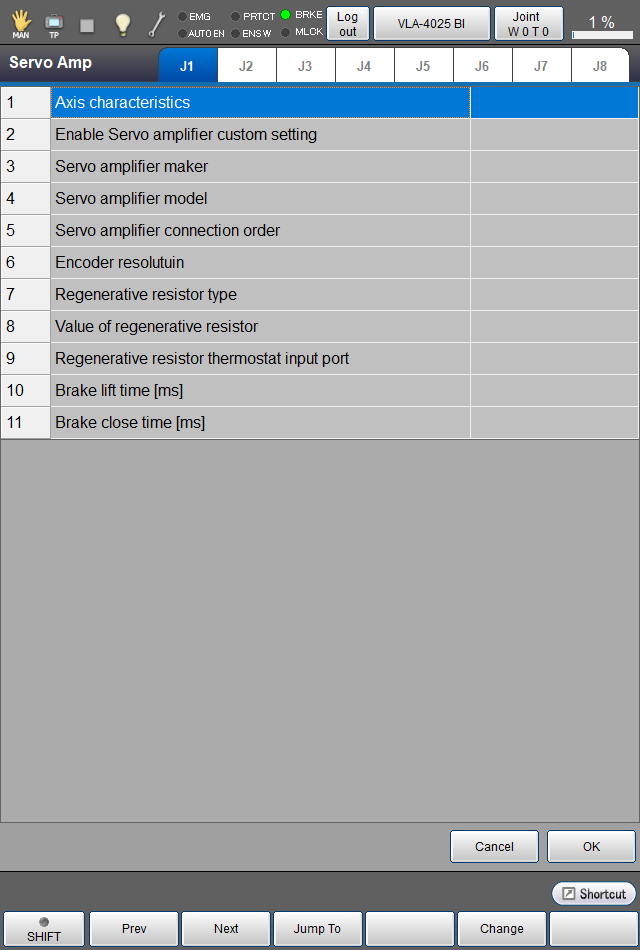
2
You can check and set servo amp parameters on the window appearing after [F6 Servo Amp] is pressed.
[Axis characteristics] is the only servo amp parameter adjustable through the smart TP.
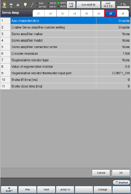
3
Select an axis tab for which you want to adjust or check the servo amp parameters.
If you have changed a value of the parameters, press [OK].
For details of each parameter, refer to the “Servo Amp Parameter List” below.
4
After adjusting and checking the parameter settings, press [OK].
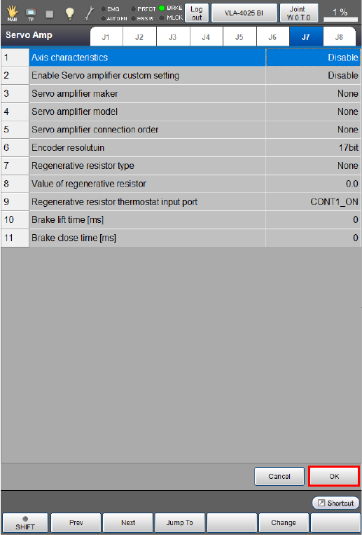
This will take you back to the [Joint Settings] window.
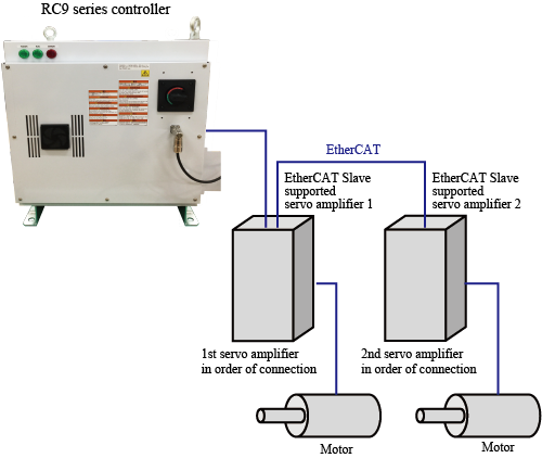
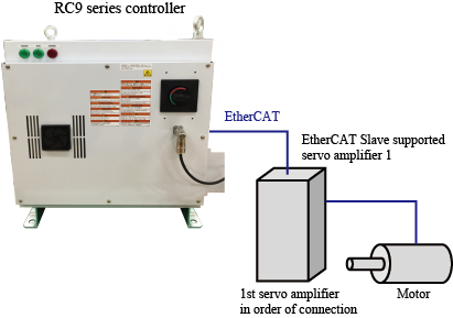
Servo Amplifier Connection Order
Servo amplifier connection order is a parameter that determines which servo amplifier will be linked to the enabled axis among the auxiliary axis amplifiers connected to the RC9 controller.
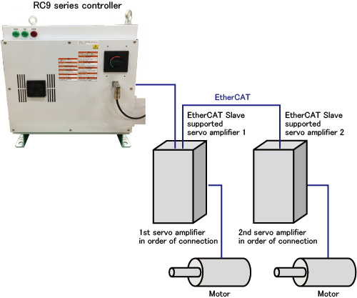
The parameter determines which servo amplifier in order of connection starting with the one nearest to the RC9 controller will be linked to the enabled auxiliary axis.
For 6-axis robots, use only [1:1st] and [2:2nd] for this parameter.
Setting this parameter improperly can cause unintended axes to start moving. Set the parameter carefully enough to avoid this.
Setting duplicate parameter values or failing to set values in the right order without skipping any number will result in the following operations.
When the parameter values are duplicate
Setting duplicate values for the parameter as shown below will link J7 to EtherCAT Slave Supported Amplifier 1 in the image below.
EtherCAT Slave Supported Amplifier 2 will neither be linked to J7 nor J8.
| Enabled axis | Servo amplifier connection order |
|---|---|
| J7 | 1:1st |
| J8 | 1:1st |
If the RC9 controller is connected to EtherCAT Slave Supported Amplifier 2 when turning on, the duplicate parameter setting causes the error "[84400A2A] EtherCAT slave device is misconnected."
Reset the parameter properly.
When the parameter values are not set in numerical order of connection
Setting the parameter values as shown below will link J7 to EtherCAT Slave Supported Amplifier 1.
| Enabled axis | Servo amplifier connection order |
|---|---|
| J7 | 2: 2nd |
Although you can operate J7 as an auxiliary axis with this setting, reset the parameter properly for safety.
When values other than 1st and 2nd are set for a 6-axis robot
Setting the parameter values as shown below will link J7 and J8 to the EtherCAT Slave Supported Amplifiers 1 and 2 respectively.
| Enabled axis | Servo amplifier connection order |
|---|---|
| J7 | 3: 3rd |
| J8 | 4: 4th |
Although you can operate J7 and J8 as auxiliary axes with this setting, reset the parameter properly for safety.
Servo Amp Parameter List
| Parameter name | Entry range | Factory default | Unit | Description | Rema0rks |
|---|---|---|---|---|---|
| Axis characteristics |
0: Enable 3: Disable |
3: Disable | Determines whether to enable or disable the axis. | ||
| Enable Servo amplifier custom setting |
0: Disable 1: Enable |
0: Disable | Determines whether to use RC9 functions for the servo amp setting or not. | For details, refer to this page. | |
| Servo amplifier maker |
0: Not set 4: DensoWave |
0: Not set | Determines the maker of the servo amplifier to be used for the auxiliary axis function. | *1 | |
| Servo amplifier model |
0: Not set 4: RC8 |
0: Not set | Determines the model of the servo amplifier to be used for the auxiliary axis function. | *1 | |
| Servo amplifier connection order |
0: Not set 1: 1st 2: 2nd 3: 3rd 4: 4th 5: 5th 6: 6th 7: 7th 8: 8th |
0: Not set | Determines which servo amplifier in numerical order of connection will be linked to the axis motor among the amplifiers connected to the RC9 controller in the daisy chain. | For details, refer to this page. | |
| Encoder resolution |
131072: 17bit |
131072: 17bit |
Determines encoder resolution to be used for the connected servo amplifiers. | ||
| Regenerative resistor type |
0: Not connected 1: Built-in 2: External |
0: Not connected | Determines whether the regenerative resistor is built-in or external. | ||
| Value of regenerative resistor | 0.0-100.0 | Ω | Determines a resistance value of the regenerative resistor. | Specify this parameter only when selecting “External” for Regenerative resistor type. | |
| Regenerative resistor thermostat input port |
-2: Not set 0:CONT1_ON 1:CONT1_OFF 2:CONT2_ON 3:CONT2_OFF 4:CONT3_ON 5:CONT3_OFF 6:CONT4_ON 7:CONT4_OFF 8:CONT5_ON 9:CONT5_OFF 10:CONT6_ON 11:CONT6_OFF 12:CONT7_ON 13:CONT7_OFF |
Determines the port for the regenerative resistor thermostat input. | Specify this parameter only when selecting “External” for Regenerative resistor type. | ||
| Brake lift time | 0-1000 | 0 | ms | Determines the delay time for the operation of the holding brake in the recommended brake release circuit. | Specify this parameter only when using a holding brake circuit, and set the proper value for the motor or the servo amplifier to be used. |
| Brake close time | 0-1000 | 0 | ms | Determines the delay time for releasing the holding brake in the recommended brake release circuit. | Specify this parameter only when using a holding brake circuit, and set the proper value for the motor or the servo amplifier to be used. |
| * 1: |
Setting an improper combination of Servo amplifier maker and Servo amplifier model will cause the error “EtherCAT slave device is misconnected.” Example
|
ID : 10972