
ID : 10975
Check the Wiring
Check the wiring of brakes and motors through the following procedure.
Check the Wiring of the Brake
To release the auxiliary axis brake through the RC9 robot controller, use the recommended brake release circuit.
You cannot operate the auxiliary axis brake through the RC9 robot controller without using the recommended circuit.
When using the recommended brake release circuit
Release the brake through the following procedure and check if the brake for the specified axis has been released.
1
Press Top Screen - [F2 Arm] - [F12 Maintenance] - [F1 Brake].
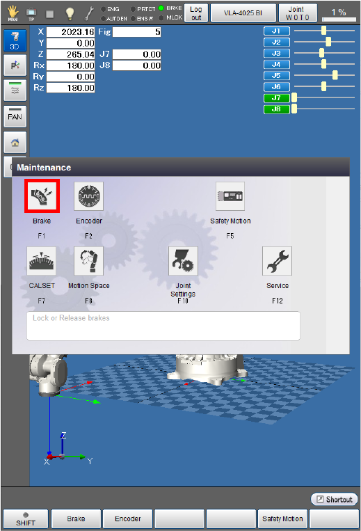
The [Brake setting] window appears.
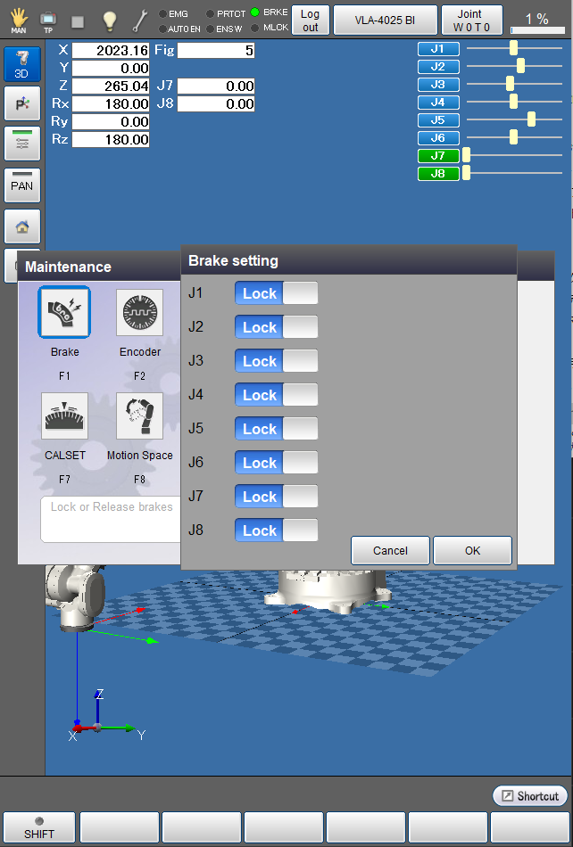
2
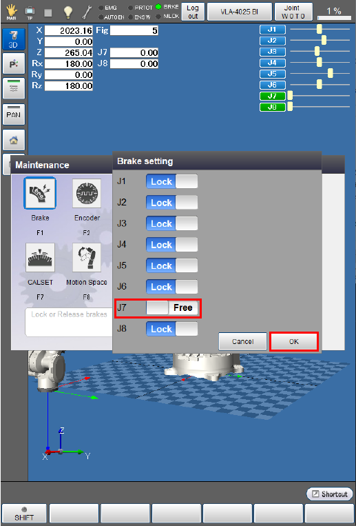
Press the button of the joint for which the brake is to be released. The indicator of the button turns into "Free".
The following examples are the displays when the 7th axes is selected.
When all brake settings are completed, press [OK].
3
A system message appears to confirm whether to change the brake settings, then press the [OK] button on the smart TP to change the settings.
This will change the brake settings and release the brake.
The brake will not be released if [Cancel] is pressed.

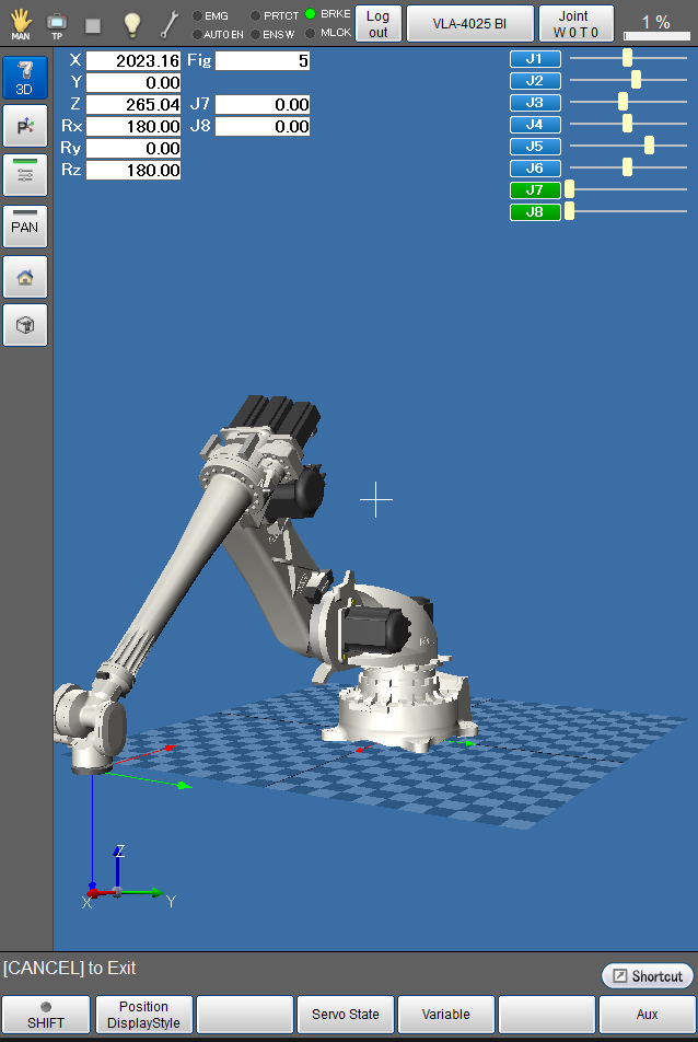
The brake is released and the [Maintenance] window appears.
4
Check if the brake has been released for the motor specified by Servo amplifier connection order.
Check if the axis for which the brake has been released can be rotated by hand.
5
Follow the path described in STEP1 to display the [Maintenance] window, and follow the procedure in STEP2 to change the state of the axis from “Free” to “Lock”, then press [OK] on the smart TP.
The brake is locked and the [Maintenance] window appears.
6
Check if the motor has been locked by the brake.
Check if the axis locked by the brake cannot be rotated by hand.
When not using the recommended brake release circuit
1
Release the motor brake through whatever methods you prefer.
Check if the axis for which the brake has been released can be rotated by hand.
2
Lock the brake through whatever methods you prefer.
Check if the axis locked by the brake cannot be rotated by hand.
Check Encoders
1
If the auxiliary axis motor has a brake, move the motor by applying an external force to it with its brake released. Check if the values for the axis linked to the motor have changed in the “current robot position” window on the smart TP.
Operation path : Top Screen - [F2 Arm]
2
- Turn on the motor.
- Use the smart TP to move the axis in Manual mode in the ± directions to check if it moves properly.
- The axis does not need to move widely in this step because this step is intended to check if it can operate in Manual mode.
- Ensure that the auxiliary axis moves in the ± directions as intended by the operation of the operation keys. If they are opposite, adjust the parameter [Polarity] in [Path Parameter].
Check the Wiring of the Motor
Turn the auxiliary axis motor on and set the motor speed at SP10, then check if the auxiliary axis can be operated manually in Joint mode.
If the motor vibrates abnormally or stops due to any error, check the wiring of the motor. If the wiring is correct, gradually decrease the positional loop gain and the speed proportional gain of the servo parameters.
ID : 10975