
ID : 10974
Servo Parameter Setting
This section describes how to set the servo parameters, which determine the gain of the auxiliary axis servo system and others.
Setting through WINCAPSIII
1
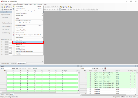
Select [Joint Setting Table] in the [Project] tab in WINCAPSIII.
2
Change the servo parameters in the [Joint Setting] tab on the [Joint Setting] screen.
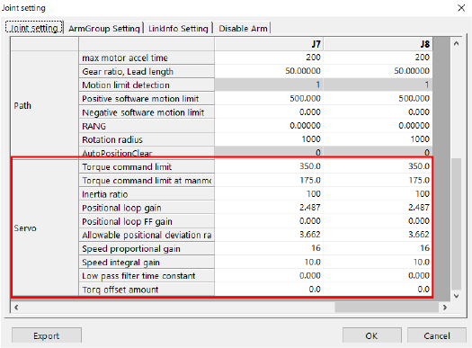
Specify the parameters you want to adjust and then press [OK].
Pressing [OK] will save the settings.
For details of each parameter, refer to the list at the bottom of this page.
Setting through the Smart TP
1
Operation path: Top screen - [F2 Arm] - [F12 Maintenance] - [F10 Joint Settings]
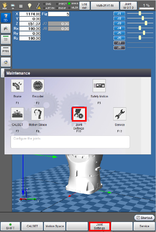
After the [Joint Settings] screen appears, press [F6 Servo Parameter].
2

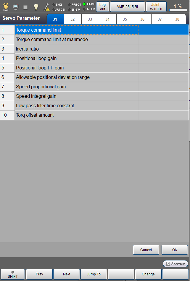
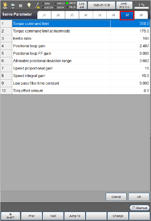
You can check and set servo parameters on the window appearing after [F6 Servo Parameter] is pressed.
3
Select an axis tab for which you want to adjust the servo parameters.
Adjust the setting of each servo parameter, then press [OK].
For details of each parameter, refer to the “Servo parameter list” at the bottom of this page.
4
After setting all the servo parameters, press [OK].

This will save the servo parameter setting and take you back to the [Joint Settings] screen.
Servo parameter list
| Parameter name | Entry range | Factory default | Unit | Description | Remarks |
|---|---|---|---|---|---|
|
Torque command limit [% to rated torque, 0 = Default] |
0 to 400 | 324 | % | Set the torque limit value to be applied in auto mode. | |
|
Torque command limit at manmode [% to rated torque, 0 = Default] |
0 to 400 | 150 | % | Set the torque limit value to be applied in manual mode. | |
| Inertia ratio[%] | 0 to 15000 | 100 | % | This parameter represents the inertia ratio calculated by (the inertia of payload / the inertia of the motor axis) * 100. | |
| Positional loop gain[Hz] | 0 to 100 | 2.487 | Hz | Set the response of the position control system. Increasing the value will decrease the positioning time. | |
| Positional loop FF gain | 0 to 2 | 0.000 | Set the loop forward gain of the position control system. Increasing the value will decrease a positioning error and increase the response, but overshoot will easily occur. | ||
| Allowable positional deviation range[rev] | 0.001 to 999.5 | 3.662 | rev | Set the allowable value of positioning error. If a positioning error exceeding this allowable value occurs, an error will result. | Set the value that meets the given formula. |
| Speed proportional gain[Hz] | 0 to 1000 | 15.803 | Hz | Set the response of the speed control system. Increasing the value will enable you to set a higher value of the positional loop gain. | |
| Speed integral gain[ms] | 0 to 100 | 10.000 | ms | Set the integral compensation gain of the speed control system. Increasing the value will converge the speed deviation at the time of stop faster. | |
| Low pass filter time constant[ms] | 0 to 327.67 | 0.532 | ms | Set the primary delay filter band in the torque instruction section. Decreasing the value will decrease the cutoff frequency of the low-pass filter. | |
|
Torque offset amount [% to rated torque] |
-100 to 100 | 0 | % | Set the torque offset value of the torque instruction value. If the motor undergoes any unbalanced load (movement towards the load), this offset will compensate it. | If you enable the gravity offset in auto gain tuning, the torque offset value will be automatically set. |
Parameter Details
Positional loop gain
Increasing the positioning loop gain will reduce the positioning time.
However, increasing the gain exceeding the natural oscillation frequency of the connected mechanism will easily bring vibration or overshoot.
As a guide, use the value of 1/2π of the natural oscillation frequency of the connected mechanism is recommended.
If the natural oscillation frequency is 20 Hz, for instance, set the positioning loop gain to 20/2/π=3.2[Hz].
Positional loop FF gain
Set the speed feeding forward value of the positioning loop. Increasing the value will reduce the positioning error and increase the system response. Setting 100 may reduce the positioning error to almost 0 in constant speed operation. However, setting an excessively high value may easily cause vibration or overshoot in the system.
Allowable positional deviation range
Set the positioning error allowance. If the actual positioning error exceeds the specified allowance, an error will occur. The positioning error allowance should satisfy the following formula.
-
[Allowable positional deviation range (rev)] > [Motor max. speed (rpm)] × (1.0-[Positional loop FF gain (%)] × 0.01)/[Positional loop gain (Hz)]/377 (*1)
*1:377 = 60*2*π
Speed proportional gain
Set the response frequency (in Hz) as a setting of the response of the speed control system. Increasing the value will enable you to set a higher value of the positional loop gain, as a result, the robot can move faster.
System automatically changes various values inside the system to achieve the entered response frequency. However, the system deems the load and inertia is 0% when setting such values. Therefore, the robot may not move along with the displayed value, depending on the actual load or inertia.
Speed integral gain
Set the integral compensation gain of the speed control system.
Increasing the value will decrease the integral time constant, making the speed error converge faster at the end of joint motion. However, increasing the value for the connected transmission mechanism having lower rigidity will decrease the convergence of residual oscillation at the end of joint motion.
Low pass filter time constant
Set the primary delay filter band in the torque instruction section.
Decreasing the value will decrease the cutoff frequency of the low-pass filter.
Torque offset amount
This value gives an offset to the torque control value of the auxiliary axis support system. If the motor undergoes any unbalanced load due to the force of gravity, setting this value will compensate the torque caused by the unbalanced load. The maximum offset value you can set is equal to the rated output torque of the motor.
If you set a large torque offset at once, the connected mechanism may move in the preset direction immediately after the motor power is turned on. Gradually change the torque offset while confirming the current torque value and positioning error waveform in the [ServoLog].
The torque offset value will be automatically set if you enable the gravity offset torque in auto gain tuning.
ID : 10974